


Primary and Supporting Method for IFR
Attitude Instrument Flying—Primary and Supporting Method
Update: 2017-02-18 The FAA has decided that they will no longer ask questions on this method on the Instrument Rating Airplane (IRA) Knowledge Test.
The Instrument Flying Handbook is the source for the questions on the FAA Knowledge Test about the primary and supporting instrument method. Bold added for emphasis. Portions were left out. A summary of the Primary and Supporting Method in Tabular form is here. I used the 2001 version in this summary because the graphics are a bit clearer, and some of the questions and answers (like the list of Pitch and Bank instruments below) are repeated verbatim on the test. This document is no longer available on the FAA website but you can download a PDF version here. The 2007 version of Instrument Flying Handbook discusses the same concepts using different graphics and using a Primary Flight Display (PFD).
Primary and Supporting Method
Another basic method for presenting attitude instrument flying classifies the instruments as they relate to control function as well as aircraft performance. All maneuvers involve some degree of motion about the lateral (pitch), longitudinal (bank/roll), and vertical (yaw) axes. Attitude control is stressed in this handbook in terms of pitch control, bank control, power control, and trim control. Instruments are grouped as they relate to control function and aircraft performance as follows:
Pitch Instruments
- Attitude Indicator
- Altimeter
- Airspeed Indicator
- Vertical Speed Indicator
Bank Instruments
- Attitude Indicator
- Heading Indicator
- Magnetic Compass
- Turn Coordinator
Power Instruments
- Airspeed Indicator
- Engine Instruments
- Manifold Pressure Gauge (MP)
- Tachometer/RPM
- Engine Pressure Ratio (EPR)—Jet
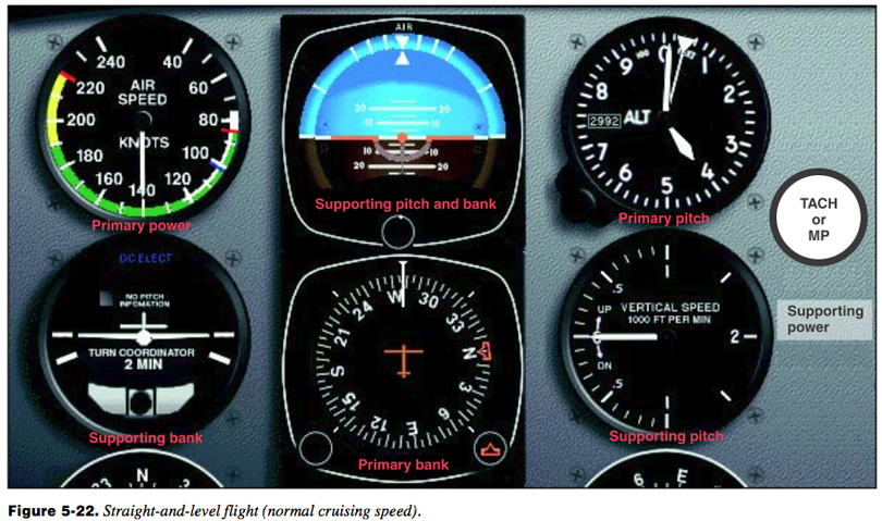
For any maneuver or condition of flight, the pitch, bank, and power control requirements are most clearly indicated by certain key instruments. The instruments that provide the most pertinent and essential information will be referred to as primary instruments. Supporting instruments back up and supplement the information shown on the primary instruments. Straight-and-level flight at a constant airspeed, for example, means that an exact altitude is to be maintained with zero bank (constant heading) at a constant airspeed. The pitch, bank, and power instruments that tell you whether you are maintaining this flight condition are the:
- 1. Altimeter—supplies the most pertinent altitude information and is therefore primary for pitch.
- 2. Heading Indicator—supplies the most pertinent bank or heading information, and is primary for bank.
- 3. Airspeed Indicator—supplies the most pertinent information concerning performance in level flight in terms of power output, and is primary for power.
Although the attitude indicator is the basic attitude reference, this concept of primary and supporting instruments does not devalue any particular flight instrument. The attitude indicator is the only instrument that portrays instantly and directly the actual flight attitude. It should always be used, when available, in establishing and maintaining pitch-and-bank attitudes. …
You will find the terms “direct indicating instrument” and “indirect indicating instrument” used in the following pages. A “direct” indication is the true and instantaneous reflection of airplane pitch-and-bank attitude by the miniature aircraft relative to the horizon bar of the attitude indicator. The altimeter, airspeed indicator, and vertical speed indicator give supporting (“indirect”) indications of pitch attitude at a given power setting. The heading indicator and turn needle give supporting indications for bank attitude.
Airplane Basic Flight Maneuvers
Straight-and-Level Flight
Pitch Control
The pitch attitude of an airplane is the angle between the longitudinal axis of the airplane and the actual horizon. In level flight, the pitch attitude varies with airspeed and load. For training purposes, the latter factor can normally be disregarded in small airplanes. At a constant airspeed, there is only one specific pitch attitude for level flight. At slow cruise speeds, the level-flight attitude is nose-high; at fast cruise speeds, the level-flight attitude is nose-low.
The pitch instruments are the attitude indicator, the altimeter, the vertical speed indicator, and the airspeed indicator.
Attitude Indicator
The attitude indicator gives you a direct indication of pitch attitude. You attain the desired pitch attitude by using the elevator control to raise or lower the miniature aircraft in relation to the horizon bar. This corresponds to the way you adjust pitch attitude in visual flight by raising or lowering the nose of the airplane in relation to the natural horizon. However, unless the airspeed is constant, and until you have established and identified the level-flight attitude for that airspeed, you have no way of knowing whether level flight, as indicated on the attitude indicator, is resulting in level flight as shown on the altimeter, vertical speed indicator, and airspeed indicator. If the miniature aircraft of the attitude indicator is properly adjusted on the ground before takeoff, it will show approximately level flight at normal cruise speed when you complete your level-off from a climb. If further adjustment of the miniature aircraft is necessary, the other pitch instruments must be used to maintain level flight while the adjustment is made.
Altimeter
At constant power, any deviation from level flight (except in turbulent air) must be the result of a pitch change. Therefore, the altimeter gives an indirect indication of the pitch attitude in level flight, assuming constant power. Since the altitude should remain constant when the airplane is in level flight, any deviation from the desired altitude signals the need for a pitch change. If you are gaining altitude, the nose must be lowered.
The rate of movement of the altimeter needle is as important as its direction of movement for maintaining level flight without the use of the attitude indicator. An excessive pitch deviation from level flight results in a relatively rapid change of altitude; a slight pitch deviation causes a slow change. Thus, if the altimeter needle moves rapidly clockwise, assume a considerable nose-high deviation from level-flight attitude. Conversely, if the needle moves slowly counterclockwise to indicate a slightly nose-low attitude, assume that the pitch correction necessary to regain the desired altitude is small.
When a pitch error is detected, corrective action should be taken promptly, but with light control pressures and two distinct changes of attitude: (1) a change of attitude to stop the needle movement, and (2) a change of attitude to return to the desired altitude.
As a rule of thumb, for errors of less than 100 feet, use a half-bar-width correction. [Figures 5-9 and 5-10] For errors in excess of 100 feet, use an initial full-bar-width correction.
Vertical Speed Indicator
The vertical speed indicator gives an indirect indication of pitch attitude and is both a trend and a rate instrument. As a trend instrument, it shows immediately the initial vertical movement of the airplane, which, disregarding turbulence, can be considered a reflection of pitch change. To maintain level flight, use the vertical speed indicator in conjunction with the altimeter and attitude indicator. Note any “up” or “down” trend of the needle from zero and apply a very light corrective elevator pressure. As the needle returns to zero, relax the corrective pressure. If your control pressures have been smooth and light, the needle will react immediately and slowly, and the altimeter will show little or no change of altitude.
Used as a rate instrument, the lag characteristics of the vertical speed indicator must be considered.
Lag refers to the delay involved before the needle attains a stable indication following a pitch change. Lag is directly proportional to the speed and magnitude of a pitch change. If a slow, smooth pitch change is initiated, the needle will move with minimum lag to a point of deflection corresponding to the extent of the pitch change, and then stabilize as the aerodynamic forces are balanced in the climb or descent. A large and abrupt pitch change will produce erratic needle movement, a reverse indication, and introduce greater time delay (lag) before the needle stabilizes. Pilots are cautioned not to chase the needle when flight through turbulent conditions produces erratic needle movements. When using the vertical speed indicator as a rate instrument and combining it with the altimeter and attitude indicator to maintain level flight, keep this in mind: the amount the altimeter has moved from the desired altitude governs the rate at which you should return to that altitude. A rule of thumb is to make an attitude change that will result in a vertical-speed rate approximately double your error in altitude. For example, if altitude is off by 100 feet, your rate of return should be approximately 200 feet per minute (fpm). If it is off more than 100 feet, the correction should be correspondingly greater, but should never exceed the optimum rate of climb or descent for your airplane at a given airspeed and configuration.
A deviation more than 200 fpm from the desired rate of return is considered overcontrolling. For example, if you are attempting to return to an altitude at a rate of 200 fpm, a rate in excess of 400 fpm indicates overcontrolling. When you are returning to an altitude, the vertical speed indicator is the primary pitch instrument. Occasionally, the vertical speed indicator is slightly out of calibration and may indicate a climb or descent when the airplane is in level flight. If you cannot adjust the instrument, you must take the error into consideration when using it for pitch control. For example, if the needle indicates a descent of 200 fpm while in level flight, use this indication as the zero position.
Airspeed Indicator
The airspeed indicator presents an indirect indication of the pitch attitude. At a constant power setting and pitch attitude, airspeed remains constant. As the pitch attitude lowers, and the nose should be lowered. A rapid change in airspeed indicates a large pitch change, and a slow change of airspeed indicates a small pitch change.
The apparent lag in airspeed indications with pitch changes varies greatly among different airplanes and is due to the time required for the airplane to accelerate or decelerate when the pitch attitude is changed. There is no appreciable lag due to the construction or operation of the instrument. Small pitch changes, smoothly executed, result in an immediate change of airspeed.
Pitch control in level flight is a question of cross-check and interpretation of the instrument panel for the instrument information that will enable you to visualize and control pitch attitude. Regardless of individual differences in cross-check technique, all pilots should use the instruments that give the best information for controlling the airplane in any given maneuver. Pilots should also check the other instruments to aid in maintaining the important, or primary, instruments at the desired indication.
As noted previously, the primary instrument is the one that gives the most pertinent information for any particular maneuver. It is usually the one you should hold at a constant indication. Which instrument is primary for pitch control in level flight, for example? This question should be considered in the context of specific airplane, weather conditions, pilot experience, operational conditions, and other factors. Attitude changes must be detected and interpreted instantly for immediate control action in high-performance airplanes. On the other hand, a reasonably proficient instrument pilot in a slower airplane may rely more on the altimeter for primary pitch information, especially if it is determined that too much reliance on the attitude indicator fails to provide the necessary precise attitude information. Whether the pilot decides to regard the altimeter or the attitude indicator as primary depends on which approach will best help control the attitude.
In this handbook, the altimeter is normally considered as the primary pitch instrument during level flight.
Bank Control
The bank attitude of an airplane is the angle between the lateral axis of the airplane and the natural horizon. To maintain a straight-and-level flight path, you must keep the wings of the airplane level with the horizon (assuming the airplane is in coordinated flight). Any deviation from straight flight resulting from bank error should be corrected by coordinated aileron and rudder pressure.
The instruments used for bank control are the attitude indicator, the heading indicator, and the turn coordinator.
Attitude Indicator
The attitude indicator shows any change in bank attitude directly and instantly. On the standard attitude indicator, the angle of bank is shown pictorially by the relationship of the miniature aircraft to the artificial horizon bar, and by the alignment of the pointer with the banking scale at the top of the instrument. On the face of the standard 3-inch instrument, small angles of bank can be difficult to detect by reference to the miniature aircraft, especially if you lean to one side or move your seating position slightly. The position of the scale pointer is a good check against the apparent miniature aircraft position. Disregarding precession error, small deviations from straight coordinated flight can be readily detected on the scale pointer. The banking index may be graduated as shown in , or it may lack the 10° and 20° indexes.
… the obvious advantage of the attitude indicator is that you get an immediate indication of both pitch attitude and bank attitude in a single glance. Even with the precession errors associated with many attitude indicators, the quick attitude presentation requires less visual effort and time for positive control than other flight instruments.
Heading Indicator
The bank attitude of an aircraft in coordinated flight is shown indirectly on the heading indicator, since banking results in a turn and change in heading. Assuming the same airspeed in both instances, a rapid movement of the heading indicator needle (or azimuth card in a directional gyro) indicates a large angle of bank, whereas a slow movement of the needle or card reflects a small angle of bank. If you note the rate of movement of the heading indicator and compare it to the attitude indicator’s degrees of bank, you will learn to look for important bank information on the heading indicator. This is especially the case when the attitude indicator’s precession error makes a precise check of heading information necessary in order to maintain straight flight.
When you note deviations from straight flight on the heading indicator, make your correction to the desired heading using a bank angle no greater than the number of degrees to be turned. In any case, limit your bank corrections to a bank angle no greater than that required for a standard-rate turn. Use of larger bank angles requires a very high level of proficiency, and normally results in overcontrolling and erratic bank control.
Turn Coordinator
The miniature aircraft of the turn coordinator gives you an indirect indication of the bank attitude of the airplane. When the miniature aircraft is level, the airplane is in straight flight. If the ball is centered, a left deflection of the miniature aircraft means the left wing is low and the airplane is in a left turn. Thus, when the miniature aircraft is in a stabilized deflection, the airplane is turning in the direction indicated. Return to straight flight is accomplished by coordinated aileron and rudder pressure to level the miniature aircraft. Include the miniature aircraft in your cross-check and correct for even the smallest deviations from the desired position. When the instrument is used to maintain straight flight, control pressures must be applied very lightly and smoothly.
The ball of the turn coordinator is actually a separate instrument, conveniently located under the miniature aircraft because the two instruments are used together. The ball instrument indicates the quality of the turn. If the ball is off center, the airplane is slipping or skidding, and the miniature aircraft under these conditions shows an error in bank attitude. Figures 5-18 and 5-19 show the instrument indications for slips and skids, respectively. If the wings are level and the airplane is properly trimmed, the ball will remain in the center, and the airplane will be in straight flight. If the ball is not centered, the airplane is improperly trimmed (or you are holding rudder pressure against proper trim).
To maintain straight-and-level flight with proper trim, note the direction of ball displacement. If the ball is to the left of center and the left wing is low, apply left rudder pressure (or release right rudder pressure if you are holding it) to center the ball and correct the slip. At the same time apply right aileron pressure as necessary to level the wings, cross- checking the heading indicator and attitude indicator as you center the ball. If the wings are level and the ball is displaced from the center, the airplane is skidding. Note the direction of ball displacement, and use the same corrective technique as for an indicated slip. Center the ball (left ball/left rudder, right ball/right rudder), use aileron as necessary for bank control, and retrim.
To trim the airplane using only the turn coordinator, use aileron pressure to level the miniature aircraft and rudder pressure to center the ball. Hold these indications with control pressures, gradually releasing them as you apply rudder trim sufficient to relieve all rudder pressure. Apply aileron trim, if available, to relieve aileron pressure. With a full instrument panel, maintain a wings-level attitude by reference to all available instruments while you trim the airplane.
Power Control
Power produces thrust which, with the appropriate angle of attack of the wing, overcomes the forces of gravity, drag, and inertia to determine airplane performance. Power control must be related to its effect on altitude and airspeed, since any change in power setting results in a change in the airspeed or the altitude of the airplane. At any given airspeed, the power setting determines whether the airplane is in level flight, in a climb, or in a descent. If you increase the power while in straight-and-level flight and hold the airspeed constant, the airplane will climb; and if you decrease the power while holding the airspeed constant, the airplane will descend. On the other hand, if you hold altitude constant, the power applied will determine the airspeed.
The relationship between altitude and airspeed determines the need for a change in pitch or power. If the airspeed is off the desired value, always check the altimeter before deciding that a power change is necessary. If you think of altitude and airspeed as interchangeable, you can trade altitude for airspeed by lowering the nose, or convert airspeed to altitude by raising the nose. If your altitude is higher than desired and your airspeed is low, or vice versa, a change in pitch alone may return the airplane to the desired altitude and airspeed. [Figure 5-20] If both airspeed and altitude are high or if both are low, then a change in both pitch and power is necessary in order to return to the desired airspeed and altitude.
For changes in airspeed in straight-and-level flight, pitch, bank, and power must be coordinated in order to maintain constant altitude and heading. When power is changed to vary airspeed in straight-and-level flight, a single-engine, propeller-driven airplane tends to change attitude around all axes of movement. Therefore, to maintain constant altitude and heading, you will need to apply various control pressures in proportion to the change in power. When you add power to increase airspeed, the pitch instruments will show a climb unless you apply forward-elevator control pressure as the airspeed changes. When you increase power, the airplane tends to yaw and roll to the left unless you apply counteracting aileron and rudder pressures. Keeping ahead of these changes requires an increase in your cross-check speed, which varies with the type of airplane and its torque characteristics, the extent of power and speed change involved, and your technique in making the power change.
Straight and Level Flight
The basic attitude is established and maintained on the attitude indicator, and the specific pitch, bank, and power control requirements are detected on these primary instruments:
Altimeter—Primary Pitch
Heading Indicator—Primary Bank
Airspeed Indicator—Primary Power
Supporting pitch-and-bank instruments are shown in the illustrations. The supporting power instrument is the manifold pressure gauge (or tachometer if the propeller is fixed-pitch).
As you make a smooth power reduction to approximately 15″ Hg (underpower), the manifold pressure gauge becomes the primary power instrument. [Figure 5-23] With practice, you will be able to change a power setting with only a brief glance at the power instrument, by sensing the movement of the throttle, the change in sound, and the changes in the feel of control pressures.
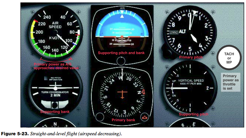
As the thrust decreases, increase the speed of your cross- check and be ready to apply left rudder, back-elevator, and aileron control pressure the instant the pitch-and-bank instruments show a deviation from altitude and heading. As you become proficient, you will learn to cross-check, interpret, and control the changes with no deviation of heading and altitude. Assuming smooth air and ideal control technique, as airspeed decreases, a proportionate increase in airplane pitch attitude is required to maintain altitude. Similarly, effective torque control means counteracting yaw with rudder pressure.
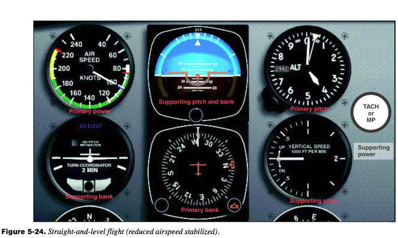
As the power is reduced, the altimeter is primary for pitch, the heading indicator is primary for bank, and the manifold pressure gauge is momentarily primary for power (at 15″ Hg in this example). Control pressures should be trimmed off as the airplane decelerates. As the airspeed approaches the desired airspeed of 100 knots, the manifold pressure is adjusted to approximately 18″ Hg and becomes the supporting power instrument. The airspeed indicator again becomes primary for power. [Figure 5-24]
Airspeed Changes in Straight-and-Level
Flight Practice of airspeed changes in straight-and-level flight provides an excellent means of developing increased proficiency in all three basic instrument skills, and brings out some common errors to be expected during training in straight-and-level flight. Having learned to control the airplane in a clean configuration (minimum drag conditions), you can increase your proficiency in cross-check and control by practicing speed changes while extending or retracting the flaps and landing gear. While practicing, be sure you comply with the airspeed limitations specified in your POH/AFM for gear and flap operation.
Sudden and exaggerated attitude changes may be necessary in order to maintain straight-and-level flight as the landing gear is extended and the flaps are lowered in some airplanes. The nose tends to pitch down with gear extension, and when flaps are lowered, lift increases momentarily (at partial flap settings) followed by a marked increase in drag as the flaps near maximum extension.
Control technique varies according to the lift and drag characteristics of each airplane. Accordingly, knowledge of the power settings and trim changes associated with different combinations of airspeed, gear and flap configurations will reduce your instrument cross-check and interpretation problems.
For example, assume that in straight-and-level flight, an airplane indicates 145 knots with power at 22″ Hg manifold pressure/2,300 RPM, gear and flaps up. After reduction in airspeed, with gear and flaps fully extended, straight-and- level flight at the same altitude requires 25″ Hg manifold pressure/2,500 RPM. Maximum gear extension speed is 125 knots; maximum flap extension speed is 105 knots. Airspeed reduction to 95 knots, gear and flaps down, can be made in the following manner:
- 1. Increase RPM to 2,500, since a high power setting will be used in full drag configuration.
- 2. Reduce manifold pressure to 10″ Hg. As the airspeed decreases, increase cross-check speed.
- 3. Make trim adjustments for an increased angle of attack and decrease in torque.
- 4. As you lower the gear at 125 knots, the nose may tend to pitch down and the rate of deceleration increases. Increase pitch attitude to maintain constant altitude, and trim off some of the back-elevator pressures. If you lower full flaps at this point, your cross-check, interpretation, and control must be very rapid. A less difficult technique is to stabilize the airspeed and attitude with gear down before lowering the flaps.
- 5. Since 18″ Hg manifold pressure will hold level flight at 95 knots with the gear down, increase power smoothly to that setting as the airspeed indicator shows approximately 100 knots, and retrim. The attitude indicator now shows approximately two-and-a-half bar width nose-high in straight-and-level flight.
- 6. Actuate the flap control and simultaneously increase power to the predetermined setting (25″ Hg) for the desired airspeed, and trim off the pressures necessary to hold constant altitude and heading. The attitude indicator now shows a bar-width nflight at 95 knots.
Trim Technique
Proper trim technique is essential for smooth and precise aircraft control during all phases of flight. By relieving all control pressures, it is much easier to hold a given attitude constant, and you can devote more attention to other cockpit duties.
Straight Climbs and Descents
Climbs
For a given power setting and load condition, there is only one attitude that will give the most efficient rate of climb. The airspeed and the climb power setting that will determine this climb attitude are given in the performance data found in your POH/AFM. Details of the technique for entering a climb vary according to airspeed on entry and the type of climb (constant airspeed or constant rate) desired. (Heading and trim control are maintained as discussed under straight- and-level flight.)
Entry
To enter a constant-airspeed climb from cruising airspeed, raise the miniature aircraft to the approximate nose-high indication for the predetermined climb speed. The attitude will vary according to the type of airplane you are flying. Apply light back-elevator pressure to initiate and maintain the climb attitude. The pressures will vary as the airplane decelerates. Power may be advanced to the climb power setting simultaneously with the pitch change, or after the pitch change is established and the airspeed approaches climb speed. If the transition from level flight to climb is smooth, the vertical speed indicator will show an immediate trend upward, continue to move slowly, then stop at a rate appropriate to the stabilized airspeed and attitude. (Primary and supporting instruments for the climb entry are shown in figure 5-25.)
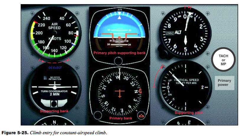
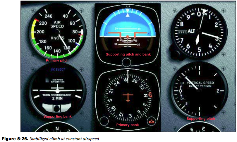
Once the airplane stabilizes at a constant airspeed and attitude, the airspeed indicator is primary for pitch and the heading indicator remains primary for bank. [Figure 5-26] You will monitor the tachometer or manifold pressure gauge as the primary power instrument to ensure the proper climb power setting is being maintained. If the climb attitude is correct for the power setting selected, the airspeed will stabilize at the desired speed. If the airspeed is low or high, make an appropriate small pitch correction.
To enter a constant-airspeed climb, first complete the airspeed reduction from cruise airspeed to climb speed in straight-and-level flight. The climb entry is then identical to entry from cruising airspeed, except that power must be increased simultaneously to the climb setting as the pitch attitude is increased. Climb entries on partial panel are more easily and accurately controlled if you enter the maneuver from climbing speed.
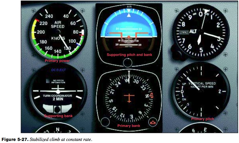
The technique for entering a constant-rate climb is very similar to that used for entry to a constant-airspeed climb from climb airspeed. As the power is increased to the approximate setting for the desired rate, simultaneously raise the miniature aircraft to the climbing attitude for the desired airspeed and rate of climb. As the power is increased, the airspeed indicator is primary for pitch control until the vertical speed approaches the desired value. As the vertical-speed needle stabilizes, it becomes primary for pitch control and the airspeed indicator becomes primary for power control. [Figure 5-27]
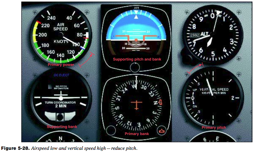
Pitch and power corrections must be promptly and closely coordinated. For example, if the vertical speed is correct, but the airspeed is low, add power. As the power is increased, the miniature aircraft must be lowered slightly to maintain constant vertical speed. If the vertical speed is high and the airspeed is low, lower the miniature aircraft slightly and note the increase in airspeed to determine whether or not a power change is also necessary. [Figure 5-28] Familiarity with the approximate power settings helps to keep your pitch and power corrections at a minimum.
Leveling Off
To level-off from a climb and maintain an altitude, it is necessary to start the level-off before reaching the desired altitude. The amount of lead varies with rate of climb and pilot technique. If your airplane is climbing at 1,000 fpm, it will continue to climb at a decreasing rate throughout the transition to level flight. An effective practice is to lead the altitude by 10 percent of the vertical speed shown (500 fpm/ 50-foot lead, 1,000 fpm/100-foot lead).
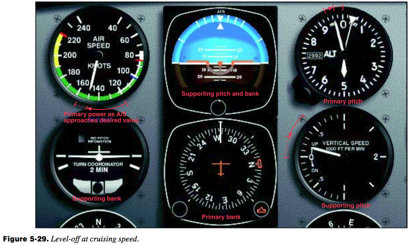
To level-off at cruising airspeed, apply smooth, steady forward-elevator pressure toward level-flight attitude for the speed desired. As the attitude indicator shows the pitch change, the vertical-speed needle will move slowly toward zero, the altimeter needle will move more slowly, and the airspeed will show acceleration. [Figure 5-29] Once the altimeter, attitude indicator, and vertical speed indicator show level flight, constant changes in pitch and torque control will have to be made as the airspeed increases. As the airspeed approaches cruising speed, reduce power to the cruise setting. The amount of lead depends upon the rate of acceleration of your airplane.
To level-off at climbing airspeed, lower the nose to the pitch attitude appropriate to that airspeed in level flight. Power is simultaneously reduced to the setting for that airspeed as the pitch attitude is lowered. If your power reduction is at a rate proportionate to the pitch change, the airspeed will remain constant.
Descents
A descent can be made at a variety of airspeeds and attitudes by reducing power, adding drag, and lowering the nose to a predetermined attitude. Sooner or later the airspeed will stabilize at a constant value. Meanwhile, the only flight instrument providing a positive attitude reference, by itself, is the attitude indicator. Without the attitude indicator (such as during a partial-panel descent) the airspeed indicator, the altimeter, and the vertical speed indicator will be showing varying rates of change until the airplane decelerates to a constant airspeed at a constant attitude. During the transition, changes in control pressure and trim, as well as cross-check and interpretation, must be very accurate if you expect to maintain positive control.
Entry
The following method for entering descents is effective either with or without an attitude indicator. First, reduce airspeed to your selected descent airspeed while maintaining straight- and-level flight, then make a further reduction in power (to a predetermined setting). As the power is adjusted, simultaneously lower the nose to maintain constant airspeed, and trim off control pressures.
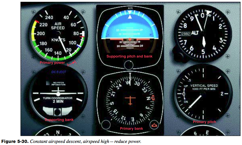
During a constant-airspeed descent, any deviation from the desired airspeed calls for a pitch adjustment. For a constant- rate descent, the entry is the same, but the vertical-speed indicator is primary for pitch control (after it stabilizes near the desired rate), and the airspeed indicator is primary for power control. Pitch and power must be closely coordinated when corrections are made, as they are in climbs. [Figure 5-30]
Leveling Off
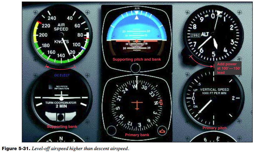
The level-off from a descent must be started before you reach the desired altitude. The amount of lead depends upon the rate of descent and control technique. With too little lead, you will tend to overshoot the selected altitude unless your technique is rapid. Assuming a 500-fpm rate of descent, lead the altitude by 100–150 feet for a level-off at an airspeed higher than descending speed. At the lead point, add power to the appropriate level-flight cruise setting. [Figure 5-31] Since the nose will tend to rise as the airspeed increases, hold forward-elevator pressure to maintain the vertical speed at the descending rate until approximately 50 feet above the altitude, then smoothly adjust the pitch attitude to the level- flight attitude for the airspeed selected.
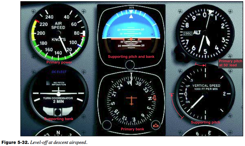
To level-off from a descent at descent airspeed, lead the desired altitude by approximately 50 feet, simultaneously adjusting the pitch attitude to level flight and adding power to a setting that will hold the airspeed constant. [Figure 5-32] Trim off the control pressures and continue with thnormal straight-and-level flight cross-check.
Turns
Standard-Rate Turns
To enter a standard-rate level turn, apply coordinated aileron and rudder pressures in the desired direction of turn. Pilots commonly roll into turns at a much too rapid rate. During initial training in turns, base your control pressures on your rate of cross-check and interpretation. There is nothing to be gained by maneuvering an airplane faster than your capacity to keep up with the changes in instrument indications. On the roll-in, use the attitude indicator to establish the approximate angle of bank, then check the turn coordinator’s miniature aircraft for a standard-rate turn indication. Maintain the bank for this rate of turn, using the turn coordinator’s miniature aircraft as the primary bank reference and the attitude indicator as the supporting bank instrument. [Figure 5-33] Note the exact angle of bank shown on the banking scale of the attitude indicator when the turn coordinator indicates a standard-rate turn.

During the roll-in, check the altimeter, vertical speed indicator, and attitude indicator for the necessary pitch adjustments as the vertical lift component decreases with an increase in bank. If constant airspeed is to be maintained, the airspeed indicator becomes primary for power, and the throttle must be adjusted as drag increases. As the bank is established, trim off the pressures applied during pitch and power changes.
To recover to straight-and-level flight, apply coordinated aileron and rudder pressures opposite the direction of turn. If you strive for the same rate of roll-out you used to roll into the turn, you will encounter fewer problems in estimating the lead necessary for roll-out on exact headings, especially on partial-panel maneuvers. As you initiate the turn recovery, the attitude indicator becomes the primary bank instrument. When the airplane is approximately level, the heading indicator is the primary bank instrument as in straight-and- level flight. Pitch, power, and trim adjustments are made as changes in vertical lift component and airspeed occur. The ball should be checked throughout the turn, especially if control pressures are held rather than trimmed off.
Some airplanes are very stable during turns, and slight trim adjustments permit hands-off flight while the airplane remains in the established attitude. Other airplanes require constant, rapid cross-check and control during turns to correct overbanking tendencies. Due to the interrelationship of pitch, bank, and airspeed deviations during turns, your cross-check must be fast in order to prevent an accumulation of errors.
Turns to Predetermined Headings
As long as an airplane is in a coordinated bank, it continues to turn. Thus, the roll-out to a desired heading must be started before the heading is reached. The amount of lead varies with the relationship between the rate of turn, angle of bank, and rate of recovery. For small heading changes, use a bank angle that does not exceed the number of degrees to be turned. Lead the desired heading by one-half the number of degrees of bank used. For example, if you maintain a 10° bank during a change in heading, start the roll-out 5° before you reach the desired heading. For larger changes in heading, the amount of lead will vary since the angle of bank for a standard-rate turn varies with the true airspeed.
Practice with a lead of one-half the angle of bank until you have determined the precise lead suitable to your technique. If your rates of roll-in and roll-out are consistent, you can readily determine the precise amount of lead suitable to your particular roll-out technique by noting the amount that you consistently undershoot or overshoot the headings.
Timed Turns
A timed turn is a turn in which the clock and the turn coordinator are used to change heading a definite number of degrees in a given time. For example, in a standard-rate turn (3° per second), an airplane turns 45° in 15 seconds; in a half-standard-rate turn, the airplane turns 45° in 30 seconds.

Prior to performing timed turns, the turn coordinator should be calibrated to determine the accuracy of its indications. [Figure 5-34] Establish a standard-rate turn as indicated by the turn coordinator, and as the sweep-second hand of the clock passes a cardinal point (12, 3, 6, 9), check the heading on the heading indicator. While holding the indicated rate of turn constant, note the indicated heading changes at 10- second intervals. If the airplane turns more or less than 30° in that interval, a larger or smaller deflection of the miniature aircraft of the turn coordinator is necessary to produce a standard-rate turn. When you have calibrated the turn coordinator during turns in each direction, note the corrected deflections, if any, and apply them during all timed turns.
The same cross-check and control technique is used in making timed turns that you use to execute turns to prede- termined headings, except that you substitute the clock for the heading indicator. The miniature aircraft of the turn coordinator is primary for bank control, the altimeter is primary for pitch control, and the airspeed indicator is primary for power control. Start the roll-in when the clock’s second hand passes a cardinal point, hold the turn at the calibrated standard rate indication (or half-standard rate for small heading changes), and begin the roll-out when the computed number of seconds has elapsed. If the rates of roll-in and roll-out are the same, the time taken during entry and recovery does not need to be considered in the time computation.
If you practice timed turns with a full instrument panel, check the heading indicator for the accuracy of your turns. If you execute the turns without the gyro heading indicator, use the magnetic compass at the completion of the turn to check turn accuracy, taking compass deviation errors into consideration.
Climbing and Descending Turns
To execute climbing and descending turns, combine the technique used in straight climbs and descents with the various turn techniques. The aerodynamic factors affecting lift and power control must be considered in determining power settings, and the rate of cross-check and interpretation must be increased to enable you to control bank as well as pitch changes.
Change of Airspeed in Turns
Changing airspeed in turns is an effective maneuver for increasing your proficiency in all three basic instrument skills. Since the maneuver involves simultaneous changes in all components of control, proper execution requires rapid cross- check and interpretation as well as smooth control. Proficiency in the maneuver will also contribute to your confidence in the instruments during attitude and power changes involved in more complex maneuvers. Pitch and power control techniques are the same as those used during changes in airspeed in straight-and-level flight.
The angle of bank necessary for a given rate of turn is proportional to the true airspeed. Since the turns are executed at a standard rate, the angle of bank must be varied in direct proportion to the airspeed change in order to maintain a constant rate of turn. During a reduction of airspeed, you must decrease the angle of bank and increase the pitch attitude to maintain altitude and a standard-rate turn.
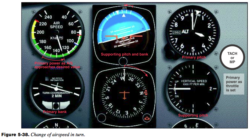
The altimeter and turn coordinator indications should remain constant throughout the turn. The altimeter is primary for pitch control and the miniature aircraft of the turn coordinator is primary for bank control. The manifold pressure gauge (or tachometer) is primary for power control while the airspeed is changing. As the airspeed approaches the new indication, the airspeed indicator becomes primary for power control.
Two methods of changing airspeed in turns may be used. In the first method, airspeed is changed after the turn is established [Figure 5-38]; in the second method, the airspeed change is initiated simultaneously with the turn entry. The first method is easier, but regardless of the method used, the rate of cross-check must be increased as you reduce power. As the airplane decelerates, check the altimeter and vertical speed indicator for needed pitch changes and the bank instruments for needed bank changes. If the miniature aircraft of the turn coordinator shows a deviation from the desired deflection, change the bank. Adjust pitch attitude to maintain altitude. When approaching the desired airspeed, it becomes primary for power control and the manifold pressure gauge (or tachometer) is adjusted to maintain the desired airspeed. Trim is important throughout the maneuver to relieve control pressures.
The 2007 version of Instrument Flying Handbook discusses the same concepts but has a slightly different emphasis, especially as related to the importance of the attitude indicator. I’ve reproduced the first few sections of the PFD version below.
The second method for performing attitude instrument flight is a direct extension of the control/power method. By utilizing the primary and supporting flight instruments in conjunction with the control and power instruments, the pilot can precisely maintain aircraft attitude. This method utilizes the same instruments as the control/power method; however, it focuses more on the instruments that depict the most accurate indication for the aspect of the aircraft attitude being controlled. The four key elements (pitch, bank, roll, and trim) are discussed in detail.
Similar to the control/power method, all changes to aircraft attitude need to be made using the attitude indicator and the power instruments (tachometer, manifold pressure gauge, etc.). The following explains how each component of the aircraft attitude is monitored for performance.
Pitch Control
The pitch of the aircraft refers to the angle between the longitudinal axis of the aircraft and the natural horizon. When flying in instrument meteorological conditions, the natural horizon is unavailable for reference, and an artificial horizon is utilized in its place. The only instrument capable of depicting the aircraft attitude is the attitude indicator displayed on the PFD. The attitude and heading reference system (AHRS) is the engine that drives the attitude display. The AHRS unit is capable of precisely tracking minute changes in the pitch, bank, and yaw axes, thereby making the PFD very accurate and reliable. The AHRS unit determines the angle between the aircraft’s longitudinal axis and the horizon line on initialization. There is no need or means for the pilot to adjust the position of the yellow chevron which represents the nose of the aircraft.
Straight-and-Level Flight
In straight-and-level flight, the pilot maintains a constant altitude, airspeed and, for the most part, heading for extended periods of time. To achieve this, three primary instruments need to be referenced in order to maintain these three variables.
Primary Pitch
When the pilot is maintaining a constant altitude, the primary instrument for pitch is the altimeter. As long as the aircraft maintains a constant airspeed and pitch attitude, the altitude should remain constant.
Two factors that cause the altitude to deviate are turbulence and momentary distractions. When a deviation occurs, a change in the pitch needs to be made on the attitude indicator. Small deviations require small corrections while large deviations require larger corrections. Pilots should avoid making large corrections that result in rapid attitude changes, for this may lead to spatial disorientation. Smooth, timely corrections should should be made to bring the aircraft back to the desired attitude.
Pay close attention to indications on the PFD. An increase in pitch of 2.5° produces a climb rate of 450 feet per minute (fpm). Small deviations do not require large attitude changes.
A rule of thumb for correcting altitude deviations is to establish a change rate of twice the altitude deviation, not to exceed 500 fpm. For example, if the aircraft is off altitude by 40 feet, 2 x 40 = 80 feet, so a descent of approximately 100 fpm allows the aircraft to return to the desired altitude in a controlled, timely fashion.
In addition to the primary instrument, there are also supporting instruments that assist the pilot in cross-checking the pitch attitude. The supporting instruments indicate trend, but they do not indicate precise attitude indications. Three instruments (vertical speed, airspeed, and altitude trend tape) indicate when the pitch attitude has changed and that the altitude is changing. When the altitude is constant, the VSI and altitude trend tape are not shown on the PFD. When these two trend indicators are displayed, the pilot is made aware that the pitch attitudchanged and may need adjustment.
The instrument cross-check necessitates utilizing these supporting instruments to better manage altitude control. The VSI and trend tape provide the pilot with information regarding the direction and rate of altitude deviations. The pilot is thus able to make correction to the pitch attitude before a large deviation in altitude occurs. The airspeed indicator depicts an increase if the pitch attitude is lowered. Conversely, when the pitch attitude increases, the pilot should note a decrease in the airspeed.
Primary Bank
When flying in instrument meteorological conditions, pilots maintain preplanned or assigned headings. With this in mind, the primary instrument for bank angle is the heading indicator. Heading changes are displayed instantaneously. The heading indicator is the only instrument that displays the current magnetic heading, provided that it is matched to the magnetic compass with all deviation adjustments accounted for.
There are supporting instruments associated with bank as well. The turn rate trend indicator shows the pilot when the aircraft is changing heading. The magnetic compass is also useful for maintaining a heading; however, it is influenced by several errors in various phases of flight.
Primary Yaw
The slip/skid indicator is the primary instrument for yaw. It is the only instrument that can indicate if the aircraft is moving through the air with the longitudinal axis of the aircraft aligned with the relative wind.
Primary Power
The primary power instrument for straight-and-level flight is the airspeed indicator. The main focus of power is to maintain a desired airspeed during level flight. No other instrument delivers instantaneous indication.
Learning the primary and supporting instruments for each variable is the key to successfully mastering attitude instrument flying. At no point does the primary and supporting method devalue the importance of the attitude indicator or the power instruments. All instruments (control, performance, primary, and supporting) must be utilized collectively.