


ADF
The FAA still has questions on using an ADF (Automatic Direction Finder) to navigate an NDB (Non-Directional Beacon) approach. The questions aren’t too hard to answer, and in fact give you some practice adding and subtracting degrees, so they aren’t all bad. Non-directional radio beacons (NDBs) are simple AM radio transmitters that were first deployed in the 1920s and ’30s along major airmail routes. These land-based NDB stations broadcast a simple omni-directional navigational signal throughout the sky. At first they needed manual tuning but now you’re only likely to see variants of the Automatic Direction Finder. Thai Technics has examples of the various kinds of ADFs over the years. Lots of planes still have them installed, but few younger pilots are comfortable with them. However, there aren’t many NDB approaches left and most of them have a GPS overlay.
From the AIM (bold and italics added):
1-1-2. Nondirectional Radio Beacon (NDB)
a. A low or medium frequency radio beacon transmits nondirectional signals whereby the pilot of an aircraft properly equipped can determine bearings and “home” on the station. These facilities normally operate in a frequency band of 190 to 535 kilohertz (kHz), according to ICAO Annex 10 the frequency range for NDBs is between 190 and 1750 kHz, and transmit a continuous carrier with either 400 or 1020 hertz (Hz) modulation. All radio beacons except the compass locators transmit a continuous three-letter identification in code except during voice transmissions.
b. When a radio beacon is used in conjunction with the Instrument Landing System markers, it is called a Compass Locator.
c. Voice transmissions are made on radio beacons unless the letter “W” (without voice) is included in the class designator (HW).
d. Radio beacons are subject to disturbances that may result in erroneous bearing information. Such disturbances result from such factors as lightning, precipitation static, etc. At night, radio beacons are vulnerable to interference from distant stations. Nearly all disturbances which affect the Automatic Direction Finder (ADF) bearing also affect the facility’s identification. Noisy identification usually occurs when the ADF needle is erratic. Voice, music or erroneous identification may be heard when a steady false bearing is being displayed. Since ADF receivers do not have a “flag” to warn the pilot when erroneous bearing information is being displayed, the pilot should continuously monitor the NDB’s identification.
This is what a typical rotating card ADF looks like, shown here above an older transponder.
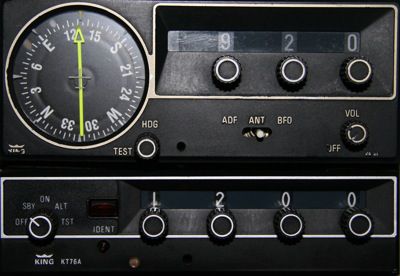
This ADF is tuned to a local AM radio station. Radio stations can be used to practice NDB approaches if you have an ADF but no local NDBs. As mentioned in the AIM, NDBs are subject to disturbances that affect the quality of the signal. This list is from Allstar Network. Stephen P. McGreevy has pictures of NDBs on his website.
- Night effect: Radio waves reflected by the ionosphere return to the earth 30 to 60 miles from the station and may cause the ADF pointer to fluctuate. The twilight effect is most pronounced during the period just before and after sunrise/sunset. Generally, the greater the distance from the station the greater the effect. The effect can be minimized by averaging the fluctuation, by flying at a higher altitude, or by selecting a station with a lower frequency (NDB transmissions on frequencies lower than 350 kHz have very little twilight effect).
- Terrain effect: Mountains or cliffs can reflect radio waves, producing a terrain effect. Furthermore, some of these slopes may have magnetic deposits that cause indefinite indications. Pilots flying near mountains should use only strong stations that give definite directional indications, and should not use stations obstructed by mountains.
- Electrical effect: When an electrical storm is nearby, the ADF needle points to the source of lightning rather than to the selected station because the lighting sends out radio waves. The pilot should note the flashes and not use the indications caused by them.
- Shoreline effect: Shorelines can refract or bend low frequency radio waves as they pass from land to water. Pilots flying over water should not use an NDB signal that crosses over the shoreline to the aircraft at an angle less than 30°. The shoreline has little or no effect on radio waves reaching the aircraft at angles greater than 30°.
- Bank effect: Bank error is present in all turns because the loop antenna which rotates to sense the direction of the incoming signal is mounted so that its axis is parallel to the normal axis of the aircraft. Bank error is a significant factor during NDB approaches.
I’ve torn out lots of articles from magazined on how to fly NDB approaches, but it took a while to find discussions on the web. Here’s an article at AOPA. Here’s a good tutorial on flying an NDB approach to Vero Beach, FL. And Allstar Network has a good explanation as well.
To solve the problems on the practical test you just have to remember one formula.
Magnetic Heading + Relative Bearing = Magnetic Bearing TO the Station.
MH + RB = MB TO the Station
If you are asked for MB From the station, it is the reciprocal.

Question: (Refer to figure 101.) What is the magnetic bearing TO the station?
Analysis: According to the DG our Magnetic Heading is 350° and our Relative Bearing is 270°. Using our formula
MH + RB = 350° + 270° = 620°. Subtract 360° to get a bearing between 0 and 360°.
Answer: The MB TO the station is 260°.
If the question asked for the MB FROM the station, we subtract 180° to get 80°.
Question: (Refer to instruments in figure 102.) On the basis of this information, the magnetic bearing TO the station would be:
Analysis: According to the DG our Magnetic Heading is 215° and our Relative Bearing is 130°. Using our formula
MH + RB = 215° + 140° = 355°. The answer is a bearing between 0 and 360°.
Answer: The MB TO the station is 355°.
If the question asked for the MB FROM the station, we subtract 180° to get 175°.
Question: (Refer to instruments in figure 103.) On the basis of this information, the magnetic bearing TO the station would be:
Analysis: According to the DG our Magnetic Heading is 330° and our Relative Bearing is 270°. Using our formula
MH + RB = 330° + 270° = 600°. Subtract 360° to get a bearing between 0 and 360°.
Answer: The MB TO the station is 240°.
If the question asked for the MB FROM the station, we subtract 180° to get 60°.
There are lots more in the same vein. Just be careful reading the indicators and with your subtraction.
They get a little trickier with a bunch that use the following image:

Question: (Refer to figure 105.) If the magnetic heading shown for aircraft 8 is maintained, which ADF illustration would indicate the aircraft is on the 090° magnetic bearing FROM the station?
Analysis: According to the picture our Magnetic Heading is 315°.
The question asks for the MB FROM so add 180° to 90° to get 270° TO.
Using our formula: MH + RB = MB TO the Station
315° + RB = 270°. Subtract 315° from both sides.
RB = -45°. The negative sign means we are 45° counterclockwise from North. This is 315°
Answer: A relative Bearing of 315° corresponds to ADF #6.