
Notes on the Instrument Procedures Handbook – Approaches
FAA-H-8083-16 Instrument Procedures Handbook
Chapter 4 Approaches
Primary NAVAID
Most conventional approach procedures are built around a primary final approach NAVAID; others, such as RNAV (GPS) approaches, are not. If a primary NAVAID exists for an approach, it should be included in the IAP briefing, set into the appropriate backup or active navigation radio, and positively identified at some point prior to being used for course guidance.
Area Navigation Courses
Approach waypoints, except for the missed approach waypoint (MAWP) and the missed approach holding waypoint (MAHWP), are normally FlyBy WPs.
Altitudes
Prescribed altitudes may be depicted in four different configurations: minimum, maximum, recommended, and mandatory.
Minimum Safe Altitude
Minimum safe altitudes (MSAs) are published for emergency use on IAP charts. For conventional navigation systems, the MSA is normally based on the primary omnidirectional facility on which the IAP is predicated.
For RNAV approaches, the MSA is based on either the runway waypoint (RWY WP), the MAWP for straight-in approaches, or the airport waypoint (APT WP) for circling only approaches. For RNAV (GPS) approaches with a terminal arrival area (TAA), the MSA is based on the IAF WP.
MSAs provide 1,000 feet clearance over all obstructions but do not necessarily assure acceptable navigation signal coverage.
Final Approach Fix Altitude
Another important altitude that should be briefed during an IAP briefing is the FAF altitude, designated by the cross on a non-precision approach, and the lightning bolt symbol designating the glideslope intercept altitude on a precision approach. Adherence and cross-check of this altitude can have a direct effect on the success and safety of an approach.
Minimum Descent Altitude (MDA), Decision Altitude (DA), And Decision Height (DH)
MDA—the lowest altitude, expressed in feet MSL, to which descent is authorized on final approach or during circle-to-land maneuvering in execution of a standard instrument approach procedure (SIAP) where no electronic glideslope is provided.
DA—a specified altitude in the precision approach at which a missed approach must be initiated if the required visual reference to continue the approach has not been established.
DH—with respect to the operation of aircraft, means the height at which a decision must be made during an ILS, MLS, or PAR IAP to either continue the approach or to execute a missed approach.
CAT II and III approach DHs are referenced to AGL and measured with a radio altimeter.
Vertical Navigation
Modern RNAV avionics can display an electronic vertical path that provides a constant-rate descent to minimums.
The pilots, airplane, and operator must be approved to use advisory VNAV inside the FAF on an instrument approach.
VNAV information appears on selected conventional nonprecision, GPS, and RNAV approaches (see “Types of Approaches” later in this chapter). It normally consists of two fixes (the FAF and the landing runway threshold), a FAF crossing altitude, a vertical descent angle (VDA), and may provide a visual descent point ( VDP).
VISUAL DESCENT POINT− A defined point on the final approach course of a nonprecision straight-in approach procedure from which normal descent from the MDA to the runway touchdown point may be commenced, provided the approach threshold of that runway, or approach lights, or other markings identifiable with the approach end of that runway are clearly visible to the pilot. (Pilot Controller Glossary) [Note: This point does not show up as a named waypoint on GPS Navigation devices or ForeFlight. It is shown on some RNAV approaches as a distance to the threshold and on some approaches with DME as a DME distance. More info at this post.]
Wide Area Augmentation System
WAAS enabled vertically guided approach procedures are called LPV, which stands for “localizer performance with vertical guidance,” and provide ILS equivalent approach minimums as low as 200 feet at qualifying airports.
RNAV (GPS) approach charts presently can have up to four lines of approach minimums: LPV, LNAV/VNAV, LNAV, and Circling.
GPS receivers (non-WAAS) can fly to the LNAV MDA.
GPS and FMS (with approach-certified barometric vertical navigation, or Baro-VNAV) can fly to the LNAV/VNAV MDA.
WAAS-LPV avionics can fly an LPV approach
If for some reason the WAAS service becomes unavailable, all GPS or WAAS equipped aircraft can revert to the LNAV MDA and land safely using GPS only, which is available nearly 100 percent of the time.
LNAV/VNAV identifies APV minimums developed to accommodate an RNAV IAP with vertical guidance, usually provided by approach certified Baro-VNAV, but with vertical and lateral integrity limits larger than a precision approach or LPV. Airplanes that are commonly approved in these types of operations include Boeing 737NG, 767, and 777, as well as the Airbus A300 series.
Ground-Based Augmentation System (GBAS)
GBAS is comprised of ground equipment and avionics. The ground equipment includes four reference receivers, a GBAS ground facility, and a VHF data broadcast transmitter. This ground equipment is complemented by GBAS avionics installed on the aircraft. Signals from GPS satellites are received by the GBAS GPS reference receivers (four receivers for each GBAS) at the GBAS equipped airport. The reference receivers calculate their position using GPS. The GPS reference receivers and GBAS ground facility work together to measure errors in GPS provided position.
The GBAS ground facility produces a GBAS correction message based on the difference between actual and GPS calculated position. Included in this message is suitable integrity parameters and approach path information. This GBAS correction message is then sent to a VHF data broadcast (VDB) transmitter. The VDB broadcasts the GBAS signal throughout the GBAS coverage area to avionics in GBAS equipped aircraft. GBAS provides its service to a local area (approximately a 20–30 mile radius). The signal coverage is designed support the aircraft’s transition from en route airspace into and throughout the terminal area airspace.
Approaches are named GLS in the TPP. GLS RWY 4L at Newark is an example.
Required Navigation Performance (RNP)
To attain the benefits of RNP approach procedures, a key component is curved flight tracks. Constant radius turns around a fix are called “radius-to-fix legs (RF legs).” These turns, which are encoded into the navigation database, allow the aircraft to avoid critical areas of terrain or conflicting airspace while preserving positional accuracy by maintaining precise, positive course guidance along the curved track. The introduction of RF legs into the design of terminal RNAV procedures results in improved use of airspace and allows procedures to be developed to and from runways that are otherwise limited to traditional linear flight paths or, in some cases, not served by an IFR procedure at all. Navigation systems with RF capability are a prerequisite to flying a procedure that includes an RF leg. Garmin GTN-series avionics should be able to fly the RF legs used as transitions/feeder routes on those approaches
Baro-VNAV
Baro-VNAV is an RNAV system function that uses barometric altitude information from the aircraft’s altimeter to compute and present a vertical guidance path to the pilot. The specified vertical path is computed as a geometric path, typically computed between two waypoints or an angle based computation from a single waypoint. Operational approval must also be obtained for Baro−VNAV systems to operate to the LNAV/VNAV minimums. Baro−VNAV may not be authorized on some approaches due to other factors, such as no local altimeter source being available. Baro−VNAV is not authorized on LPV procedures.
Hot and Cold Temperature Limitations
A minimum and maximum temperature limitation is published on procedures that authorize Baro−VNAV operation.
e.g. RNAV (GPS) RWY 11 KSPB Note: For uncompensated Baro VNAV systems, LNAV/VNAV NA below -15°C or above 42°C.
Transition to a Visual Approach
The visibility published on an approach chart is dependent on many variables, including the height above touchdown for straight-in approaches or height above airport elevation for circling approaches. Other factors include the approach light system coverage, and type of approach procedure, such as precision, non-precision, circling or straight-in. Another factor determining the minimum visibility is the penetration of the 34:1 and 20:1 surfaces. These surfaces are inclined planes that begin 200 feet out from the runway and extend outward to the DA point (for approaches with vertical guidance), the VDP location (for non-precision approaches) and 10,000 feet for an evaluation to a circling runway. If there is a penetration of the 34:1 surface, the published visibility can be no lower than three-fourths SM. If there is penetration of the 20:1 surface, the published visibility can be no lower than 1 SM with a note prohibiting approaches to the affected runway at night (both straight-in and circling).
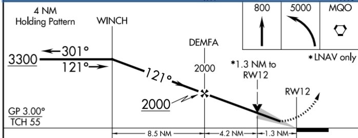
For RNAV approaches only, the presence of a grey shaded line from the MDA to the runway symbol in the profile view is an indication that the visual segment below the MDA is clear of obstructions on the 34:1 slope. Absence of the gray shaded area indicates the 34:1 OCS is not free of obstructions.
Missed Approach
Many reasons exist for executing a missed approach. The primary reasons, of course, are that the required flight visibility prescribed in the IAP being used does not exist.
In addition, according to 14 CFR Part 91, the aircraft must continuously be in a position from which a descent to a landing on the intended runway can be made at a normal rate of descent using normal maneuvers, and for operations conducted under Part 121 or 135, unless that descent rate allows touchdown to occur within the TDZ of the runway of intended landing.
A clearance for an instrument approach procedure includes a clearance to fly the published missed approach procedure, unless otherwise instructed by ATC. Once descent below the DA, DH, or MDA is begun, a missed approach must be executed if the required visibility is lost or the runway environment is no longer visible, unless the loss of sight of the runway is a result of normal banking of the aircraft during a circling approach.
Course Reversal
On U.S. Government charts, a barbed arrow indicates the maneuvering side of the outbound course on which the procedure turn is made. Headings are provided for course reversal using the 45° type procedure turn. However, the point at which the turn may be commenced and the type and rate of turn is left to the discretion of the pilot (limited by the charted remain within XX NM distance). Some of the options are the 45° procedure turn, the racetrack pattern, the teardrop procedure turn, or the 80° procedure turn, or the 80° 260° course reversal. Racetrack entries should be conducted on the maneuvering side where the majority of protected airspace resides.
Some procedure turns are specified by procedural track. These turns must be flown exactly as depicted.
Descent to the PT completion altitude from the PT fix altitude (when one has been published or assigned by ATC) must not begin until crossing over the PT fix or abeam and proceeding outbound.
A holding pattern in lieu of procedure turn may be specified for course reversal in some procedures. In such cases, the holding pattern is established over an intermediate fix or a FAF. The holding pattern distance or time specified in the profile view must be observed. If pilots elect to make additional circuits to lose excessive altitude or to become better established on course, it is their responsibility to so advise ATC upon receipt of their approach clearance.
Initial Approach Segment
The purposes of the initial approach segment are to provide a method for aligning the aircraft with the intermediate or final approach segment and to permit descent during the alignment. This is accomplished by using a DME arc, a course reversal, such as a procedure turn or holding pattern, or by following a terminal route that intersects the final approach course. The initial approach segment begins at an IAF and usually ends where it joins the intermediate approach segment or at an IF.
Many RNAV approaches make use of a dual-purpose IF/IAF associated with a hold-in-lieu-PT (HILPT) anchored at the Intermediate Fix. The HILPT forms the Initial Approach Segment when course reversal is required.
Intermediate Approach Segment
The intermediate segment is designed primarily to position the aircraft for the final descent to the airport. Like the feeder route and initial approach segment, the chart depiction of the intermediate segment provides course, distance, and minimum altitude information.
In some cases, an IF is not shown on an approach chart. In this situation, the intermediate segment begins at a point where you are proceeding inbound to the FAF, are properly aligned with the final approach course, and are located within the prescribed distance prior to the FAF.
Final Approach Segment
The final approach segment for an approach with vertical guidance or a precision approach begins where the glideslope intercepts the minimum glideslope intercept altitude shown on the approach chart.
For a non-precision approach, the final approach segment begins either at a designated FAF, which is depicted as a cross on the profile view, or at the point where the aircraft is established inbound on the final approach course.
There are three types of procedures based on the final approach course guidance:
• Precision approach (PA)—an instrument approach based on a navigation system that provides course and glidepath deviation information meeting precision standards of ICAO Annex 10. For example, PAR, ILS, and GLS are precision approaches.
• Approach with vertical guidance (APV) —an instrument approach based on a navigation system that is not required to meet the precision approach standards of ICAO Annex 10, but provides course and glidepath deviation information. For example, Baro-VNAV, LDA with glidepath, LNAV/VNAV and LPV are APV approaches.
• Non-precision approach (NPA)—an instrument approach based on a navigation system that provides course deviation information but no glidepath deviation information. For example, VOR, TACAN, LNAV, NDB, LOC, and ASR approaches are examples of NPA procedures.
Missed Approach Segment
The missed approach segment begins at the MAP and ends at a point or fix where an initial or en route segment begins.
Precision or an APV approach, the MAP occurs at the DA or DH on the glideslope.
For non-precision approaches, the MAP is either a fix, NAVAID, or after a specified period of time has elapsed after crossing the FAF.
Vectors To Final Approach Course
The approach gate is an imaginary point used within ATC as a basis for vectoring aircraft to the final approach course. The gate is established along the final approach course one mile from the FAF on the side away from the airport and is no closer than 5 NM from the landing threshold.
The controller should always assign an altitude to maintain until the aircraft is established on a segment of a published route or IAP.
Visual and Contact Approaches
To expedite traffic, ATC may clear pilots for a visual approach in lieu of the published approach procedure if flight conditions permit. Requesting a contact approach may be advantageous since it requires less time than the published IAP and provides separation from IFR and special visual flight rules (SVFR) traffic. A contact or visual approach may be used in lieu of conducting a SIAP, and both allow the flight to continue as an IFR flight to landing while increasing the efficiency of the arrival.
For a visual approach clearance, the controller must verify that pilots have the airport, or a preceding aircraft that they are to follow, in sight. May be assigned by ATC. It is authorized when the ceiling is reported or expected to be at least 1,000 feet AGL and the visibility is at least 3 SM.
Contact Approaches
Pilots can request a contact approach, which is then authorized by the controller. A contact approach cannot be initiated by ATC. The airport must have a SIAP the reported ground visibility is at least 1 SM, and pilots are able to remain clear of clouds with at least one statute mile flight visibility throughout the approach.
Terminal Arrival Areas
TAAs are the method by which aircraft equipped with a FMS and/or GPS are transitioned from the RNAV en route structure to the terminal area with minimal ATC interaction.
ILS Approach Categories
There are three general classifications of ILS approaches: CAT I, CAT II, and CAT III (autoland). The basic ILS approach is a CAT I approach and requires only that pilots be instrument rated and current, and that the aircraft be equipped appropriately. CAT II and CAT III ILS approaches typically have lower minimums and require special certification for operators, pilots, aircraft, and airborne/ground equipment. Because of the complexity and high cost of the equipment, CAT III ILS approaches are used primarily in air carrier and military operations.