
ILS
The ILS system may be divided functionally into three parts:
(a) Guidance information: localizer, glide slope;
(b) Range information: marker beacon, DME; and
(c) Visual information: approach lights, touchdown and centerline lights, runway lights
Guidance Information
Localizer transmitter operates on one of 40 ILS channels within the frequency range of 108.10 to 111.95 MHz. Located near the opposite end of the landing runway. It is adjusted for a course width of (full scale fly−left to a full scale fly−right) of 700 feet at the runway threshold.
Identification is in International Morse Code and consists of a three−letter identifier preceded by the letter I (• •) transmitted on the localizer frequency.
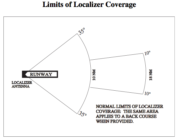
The localizer provides course guidance throughout the descent path to the runway threshold from a distance of 18 NM from the antenna between an altitude of 1,000 feet above the highest terrain along the course line and 4,500 feet above the elevation of the antenna site.
Operational service volume:
(a) To 10 degrees either side of the course along a radius of 18 NM from the antenna; and
(b) From 10 to 35 degrees either side of the course along a radius of 10 NM.
Note that there are some exceptions to this. The LAX ILS or LOC Rwy 24 and 25 approaches start on the localizer about 40 miles from the threshold.
It is similar to a VOR signal except that it provides radial information for only a single course; the runway heading. The localizer course needle is four times as sensitive as a VOR needle. Heading adjustments must be much smaller because of the increased sensitivity of the indicator. When tracking VOR radial, each dot under represents 2° deviation from course.
For the localizer each dot under the needle represents 0.5° deviation from course.
In addition to being much closer to the source than with a VOR, pilots need to remember that the localizer course is very narrow—normally 5°. This results in high needle sensitivity. With this course width, a full-scale deflection shows when the aircraft is 2.5° to either side of the centerline. This sensitivity permits accurate orientation to the landing runway. With no more than one-quarter scale deflection maintained, the aircraft will be aligned with the runway.
Near the Outer Marker, a one-dot deviation puts you about 500 ft. from the centerline. Near the Middle Marker, one dot means you’re off course by 150 ft.
LDA is similar to a localizer but is not aligned with the runway. Straight−in minimums may be published where alignment does not exceed 30 degrees between the course and runway. Only circling minimums are published where this alignment exceeds 30 degrees.
There aren’t that many of them but you can find them by doing a search for “LDA RWY ”. Examples are HFD Rwy 2 in Hartford, Connecticut and LDA Y Rwy 19 at Reagan National. Note that the arrow on the localizer portion is shaded on the RHS indicating that it is the front course. There is no glide slope and, in the case of Reagan, the MDA is 3.4 miles from the airport and the chart indicates that the offset in degrees from the runway is 37.50°.
KMTN LDA RWY 33 on the other hand does have a glide slope (as indicated by the lightning bolt on the vertical profile section of the chart. The legend LDA/GLIDE SLOPE is on the chart is also a big hint. This appears to be a case where everything is the same as an ILS, except that because the runway is lined up with the bay, the didn’t put in approach lighting so it doesn’t qualify as an ILS. This approach has a letter after the approach type, which indicates that the approach is not straight in.
KROA LDA Y RWY 6 has a glide slope, and has different minimums if you are using the glide slope or the localizer. The final approach course is 72° for runway 6 so you can see why it is an LDA not an ILS.
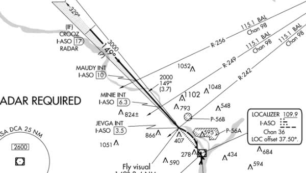
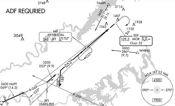
An SDF is also similar to a localizer but the course width is wider, either 6° or 12°. There are very few left. KMOR SDF RWY5 is still active and the KMFI SDF RWY 34 still shows up on the chart, but the SDF is out of service and it must be flown using GPS (2018-10-29). Note that the arrow on the localizer portion is not shaded as it is on an ILS or backcourse and the identifier box says SDF instead of Localizer. They do not have a glide slope.
Glide Slope/Glide Path frequency is paired with the localizer. The glideslope transmitter is located between 750 feet and 1,250 feet from the approach end of the runway and offset 250 to 650 feet from the runway centerline. It transmits a glide path beam 1.4 degrees wide. The glide path may not be suitable for navigation below the lowest authorized DH.
The GS projection angle is normally adjusted to 2.5° to 3.5° above horizontal, so it intersects the MM at about 200 feet and the OM at about 1,400 feet above the runway elevation. The glide slope is normally usable to the distance of 10 NM. At 10 NM from the point of touchdown, this represents a vertical distance of approximately 1,500 feet, narrowing to a few feet at touchdown.
At the Outer Marker, each dot of glide slope deviation equals about a 50-foot excursion from the prescribed glidepath. Less as you get closer to the runway.
Range Information
Distance Measuring Equipment (DME) in lieu of the OM or as a back course (BC) final approach fix (FAF).
Marker Beacons
The Outer Marker (OM) normally indicates a position at which an aircraft at the appropriate altitude on the localizer course will intercept the ILS glide path. Blue light—three dashes.
The MM indicates a position approximately 3,500 feet from the landing threshold at an altitude of approximately 200 feet above the TDZE. Amber light—dash dot dash dot.
IM will indicate a point at which an aircraft is at a designated decision height (DH) on the glide path between the MM and landing threshold. White light—four dots.
A back course marker normally indicates the ILS back course final approach fix where approach descent is commenced. White light—dot dot space dot dot.
GPS may be used in lieu of compass locator, outer and inner markers, and/or DME. Requires current database or verification that the procedure has not been amended since the expiration of the database.
Range information is also provided by radials from off-course VORs.
You may use certified GPS to:
Determine aircraft position relative to or distance from a VOR, TACAN, NDB, compass locator, DME fix; or a named fix defined by a VOR radial, TACAN course, NDB bearing, or compass locator bearing intersecting a VOR or Localizer (LOC) course. AC 90-108
Visual Information—Category I
§91.175 Takeoff and landing under IFR.
(a) Instrument approaches to civil airports. Unless otherwise authorized by the FAA, when it is necessary to use an instrument approach to a civil airport, each person operating an aircraft must use a standard instrument approach procedure prescribed in part 97 of this chapter for that airport…
(1) The aircraft is continuously in a position from which a descent to a landing on the intended runway can be made at a normal rate of descent using normal maneuvers, and for operations conducted under part 121 or part 135 unless that descent rate will allow touchdown to occur within the touchdown zone of the runway of intended landing;
(2) The flight visibility is not less than the visibility prescribed in the standard instrument approach being used; and [Note: This applies to all aircraft—not just those operating under Part 121 or 135.]
(c) Operation below DA/ DH or MDA. Except as provided in paragraph (l) of this section, where a DA/DH or MDA is applicable, no pilot may operate an aircraft, except a military aircraft of the United States, below the authorized MDA or continue an approach below the authorized DA/DH unless—
(3) Except for a Category II or Category III approach… at least one of the following visual references for the intended runway is distinctly visible and identifiable to the pilot:
(i) The approach light system, except that the pilot may not descend below 100 feet above the touchdown zone elevation using the approach lights as a reference unless the red terminating bars or the red side row bars are also distinctly visible and identifiable.
(ii) The threshold.
(iii) The threshold markings.
(iv) The threshold lights.
(v) The runway end identifier lights.
(vi) The visual approach slope indicator.
(vii) The touchdown zone or touchdown zone markings.
(viii) The touchdown zone lights.
(ix) The runway or runway markings.
(x) The runway lights.
As a guide to remembering the items, this list (in the order they appear), helps.
approach light system allows you to descend to 100′ above TDZE
runway end identifier lights (REIL, the flashing strobes on either side of the threshold)
the threshold (itself, the markings, or lights)
visual glideslopes (VASI, PAPI, etc.)
the touchdown zone (itself, the markings, or lights)
the runway (itself, the markings, or lights)
The MALSR (Medium Intensity Approach Lighting System With Runway Alignment Indicator Lights) is a medium approach intensity lighting system (ALS) installed in airport runway approach zones along the extended centerline of the runway. The MALSR, consisting of a combination of threshold lamps, steady burning light bars and flashers, provides visual information to pilots on runway alignment, height perception, roll guidance, and horizontal references for Category I Precision Approaches. There are approximately 900 MALSR in the National Airspace System (NAS).
The ALSF-2 provides visual information on runway alignment, height perception, roll guidance, and horizontal references for Category II/III instrument approaches. There are 153 commissioned facilities in the NAS.
The approach plate shows the type of approach lighting that is available and gives a graphical representation in the Pilot Briefing section of the plate as well as the location of the lighting in the Airport Diagram section.
The Runway End Identifier Lights (REIL) system provides rapid and positive identification of the end of the runway. The system consists of two synchronized, unidirectional flashing lights. The lights are positioned on each corner of the runway landing threshold, facing the approach area and aimed at an angle of 10 to 15 degrees. There are currently approximately 800 REIL systems deployed in the NAS. (It appears that they are found on runways with non-precision approaches and on the other end of an ILS approach runway.)
Runway Alignment Indicator Lights (RAIL) are high-intensity sequenced flashing lights which are installed in combination with other light systems. Also known as the rabbit.
Landing Minimums
§91.175 (d) Landing. No pilot operating an aircraft, except a military aircraft of the United States, may land that aircraft when… the flight visibility is less than the visibility prescribed in the standard instrument approach procedure being used.
ATC provides the pilot with the current visibility reports appropriate to the runway in use. This may be in the form of prevailing visibility, runway visual value (RVV), or runway visual range (RVR). However, only the pilot can determine if the flight visibility meets the landing requirements indicated on the approach chart. If the flight visibility meets the minimum prescribed for the approach, then the approach may be continued to a landing. If the flight visibility is less than that prescribed for the approach, then the pilot must execute a missed approach regardless of the reported visibility. Instrument Flying Handbook
The landing minimums published on IAP charts are based on full operation of all components and visual aids associated with the instrument approach chart being used. Higher minimums are required with inoperative components or visual aids. Instrument Flying Handbook
Operating Below DA/DH or MDA
§91.175 (c) Operation below DA/DH or MDA. …No pilot may operate an aircraft, except a military aircraft of the United States, below the authorized MDA or continue an approach below the authorized DA/DH unless—
(1) The aircraft is continuously in a position from which a descent to a landing on the intended runway can be made at a normal rate of descent using normal maneuvers, and for operations conducted under part 121 or part 135 unless that descent rate will allow touchdown to occur within the touchdown zone of the runway of intended landing;
(2) The flight visibility is not less than the visibility prescribed in the standard instrument approach being used.
Level off at an MDA is acceptable until reaching the MAP, but never permitted when the approach has vertical guidance with a DA. The DA is the altitude where you decide to initiate the missed approach or have the required visual cues to continue the landing. The point 100 feet above the runway TDZE is not a new MDA for either a vertically guided approach or a non precision approach.
The whole point of the approach light systems is to aid the pilot in getting to the runway in low visibility conditions. At the typical ILS Category I [The category most GA planes are certified for.] approach with minimums of 200 feet and a half mile, when the conditions are truly at minimums, geometry says it is impossible to see the runway threshold at the DA as it is 0.72 miles away. That is why when the ALS is OOS [Out of Service], visibility minimums go the 0.75 mile. So the approach lights guide the pilot to the point they must be able to see the other cues or abandon the approach. At 100 feet above the TDZE, the pilot is 0.36 miles from the threshold. If you can’t see one of the other runway cues, then the flight visibility is below minimums. When there is an ALSF-I system installed, the red terminating bars are within a hundred feet of the threshold and with an ALSF-II is installed, the red side row bars are located in 100 foot increments beginning 900 feet from the threshold and ending at 100 feet before the runway threshold. You must be able to see all of the side row bars. In effect, either is a visual cue that indicates the runway end is in the immediate vicinity.
When there is an approach lighting system such as the MALSF/MALSR installed, there are no red side row or terminating bars. If you clearly have the approach lights at the DA/MDA, you may continue the descent, but by 100 feet above the TDZE, you must have one of the other visual cues to continue the descent as the red side row/threshold bars don’t exist. John D Collins
The lowest authorized ILS minimums, with all required ground and airborne systems components operative, are:
(a) Category I. Decision Height (DH) 200 feet and Runway Visual Range (RVR) 2,400 feet (with touchdown zone and centerline lighting, RVR 1,800 feet), or (with Autopilot or FD or HUD, RVR 1,800 feet)
When the localizer fails, an ILS approach is not authorized. When the glide slope fails, the ILS reverts to a non−precision localizer approach.
Simplified Directional Facility (SDF)
An SDF is similar to a localizer except that the the SDF antenna may be offset from the runway centerline. Because of this, the angle of convergence between the final approach course and the runway bearing should be determined by reference to the instrument approach procedure chart. This angle is generally not more than 3 degrees. SDF signal is fixed at either 6 degrees or 12 degrees as necessary to provide maximum flyability and optimum course quality. There aren’t that many of them but you can find them by doing a search for “SDF RWY ”. Examples are the KMOR SDF Rwy 5 at Morristown, Tennessee and SDF Rwy 34 at Marshfield, Wisconsin. These are both straight-in approaches. The symbol on the chart is not shaded on one side like the symbols for the ILS/LOC and LDA because no glide slope is provided.
§91.175 Takeoff and landing under IFR.
(k) ILS components. The basic components of an ILS are the localizer, glide slope, and outer marker, and, when installed for use with Category II or Category III instrument approach procedures, an inner marker. The following means may be used to substitute for the outer marker: Compass locator; precision approach radar (PAR) or airport surveillance radar (ASR); DME, VOR, or nondirectional beacon fixes authorized in the standard instrument approach procedure; or a suitable RNAV system in conjunction with a fix identified in the standard instrument approach procedure. Applicability of, and substitution for, the inner marker for a Category II or III approach is determined by the appropriate 14 CFR part 97 approach procedure, letter of authorization, or operations specifications issued to an operator.
Cody Johnson explains how to use the 100′ rule and when one pilot descended below 100′ when there were obstructions in the way and he mis-interpreted what the approach allowed him to do.
Section 91.129(e)(3), Operations in Class D Airspace, is also extremely applicable in this accident. It says, ‘An airplane approaching to land on a runway served by a visual approach slope indicator shall maintain an altitude at or above the glide slope until a lower altitude is necessary for safe landing.’
If the pilot followed this rule he would be alive today.
§91.129 Operations in Class D airspace. (2) Each pilot operating a large or turbine-powered airplane approaching to land on a runway served by an instrument approach procedure with vertical guidance, if the airplane is so equipped, must:
(i) Operate that airplane at an altitude at or above the glide path between the published final approach fix and the decision altitude (DA), or decision height (DH), as applicable; or
Oddly enough, there does not appear to be a rule saying that you have to follow the glideslope down to the runway if you are a small airplane. But it makes sense that you should.
Class C and B incorporate Section 91.129(e)(3) by reference, so the rule applies in that airspace as well. It doesn’t specifically apply to operations at airports in Class E airspace, but they don’t typically (ever?) have ILS approaches.