
Notes from the Instrument Procedures Handbook – En Route
FAA-H-8083-16 Instrument Procedures Handbook
Chapter 2 En Route
The en route phase of flight is defined as that segment of flight from the termination point of a departure procedure to the origination point of an arrival procedure.
En Route Airspace Structure
Low Altitude Victor Airways:
Use Navaids
1,200′ AGL – 18,000′ MSL
High Altitude Jet Routes
18,000′ – FL450
Above FL450
Random operations allowed
Air Route Traffic Control Center
A facility established to provide air traffic control (ATC) service to aircraft operating on IFR flight plans within controlled airspace, principally during the en route phase of flight. When equipment capabilities and controller workload permit, certain advisory/assistance services may be provided to VFR aircraft.
Aircraft are separated by the following criteria:
• Laterally—
5 miles
• Vertically—
1,000 feet (if the aircraft is below FL290, or between FL290 and FL410 for RVSM compliant aircraft)
2,000 feet (if the aircraft is at FL290 or above)
High Altitude Area Navigation Routing
Special high altitude routes allow pilots routing options for flight within the initial high altitude routing (HAR) Phase I expansion airspace. Pilots are able to fly user-preferred routes, referred to as non-restrictive routing (NRR), between specific fixes described by pitch (entry into) and catch (exit out of) fixes in the HAR airspace. Pitch points indicate an end of departure procedures, preferred IFR routings, or other established routing programs where a flight can begin a segment of NRR. The catch point indicates where a flight ends a segment of NRR and joins published arrival procedures, preferred IFR routing, or other established routing programs.
Above FL 350 in fourteen of the western and soutern ARTCCs
Chart Supplement has pitch and catch points.

RNAV routes – Q Routes
Published as preferred IFR routes.
Preferred IFR Routes
Preferred IFR routes are established between busier airports to increase system efficiency and capacity.
Published in the Chart Supplement for low and high stratum.
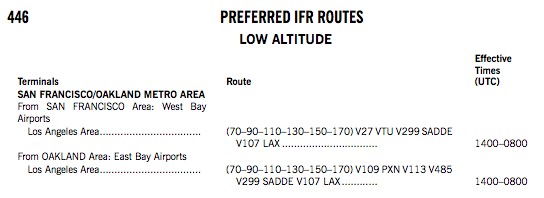
Tower En Route Control
An ATC program available to pilots that provides a service to aircraft proceeding to and from metropolitan areas.
Fly an IFR flight without leaving approach control airspace.
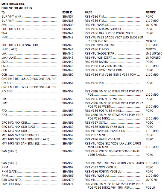
Altitudes and routes depend on aircraft classification: J-Jet, M—Turbo-Props, P—Non-Jet cruise speed > 190 kts, Q—Non-Jet cruise speed < 190 kts.
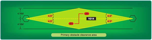
Primary and Secondary En Route Obstacle Clearance Areas
The primary obstacle clearance area has a protected width of 8 NM with 4 NM on each side of the centerline. The primary area has widths of route protection based upon system accuracy of a ±4.5° angle from the NAVAID. These 4.5° lines extend out from the NAVAID and intersect the boundaries of the primary area at a point approximately 51 NM from the NAVAID. Ideally, the 51 NM point is where pilots would change over from navigating away from the facility, to navigating toward the next facility, although this ideal is rarely achieved.
If the distance from the NAVAID to the change-over point (COP) is more than 51 NM, the outer boundary of the primary area extends beyond the 4 NM width.
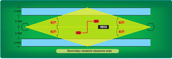
Secondary Obstacle Area has 500′ obstacle clearance.
Direct Route Flights
Direct route flights are flights that are not flown on the radials or courses of established airways or routes. Direct route flights must be defined by indicating the radio fixes over which the flight passes. Fixes selected to define the route should be those over which the position of the aircraft can be accurately determined. Such fixes automatically become compulsory reporting points for the flight, unless advised otherwise by ATC.
Operational Service Volume Limits
1. Operations above FL 450—use NAVAIDs not more than 200 NM apart. These aids are depicted on en route high altitude charts.
2. Operation off established routes from 18,000 feet MSL to FL 450—use NAVAIDs not more than 260 NM apart. These aids are depicted on en route high altitude charts.
3. Operation off established airways below 18,000 feet MSL—use NAVAIDs not more than 80 NM apart. These aids are depicted on en route low altitude charts.
4. Operation off established airways between 14,500 feet MSL and 17,999 feet MSL in the conterminous United States—(H) facilities not more than 200 NM apart may be used.
Published RNAV Routes
Published RNAV routes are fixed, permanent routes that can be flight planned and flown by aircraft with RNAV capability.
OROCA – Off-Route Obstruction Clearance Altitude
An OROCA is an off-route altitude that provides obstruction clearance with a 1,000 foot buffer in non-mountainous terrain areas and a 2,000 foot buffer in designated mountainous areas within the United States. This altitude may not provide signal coverage from ground-based NAVAIDs, ATC radar, or communications coverage.
OROCAs depicted on en route charts do not provide the pilot with an acceptable altitude for terrain and obstruction clearance for the purposes of off-route, random RNAV direct flights in either controlled or uncontrolled airspace.
When accepting a clearance below the MEA, MIA, MVA, or the OROCA, you are responsible for your own terrain/ obstruction clearance until reaching the MEA, MIA, or MVA.
When you plan a random RNAV route, I would suggest you don’t restrict yourself to just the IFR enroute charts. I also look at sectional charts. They also depict a Maximum Elevation Figure (MEF) which may be used for altitude planning, but its dimensions are 30 minutes of latitude and longitude whereas the OROCA altitude covers an area of 1 degree of latitude and longitude, so there are 4 times the detail. If you use the MEF, remember that you have to add 1000 feet or 2000 feet (mountainous) to get to an equivalent to the OROCA, as the MEF only has a buffer of at most a few hundred feet and it depicts the MSL altitude of the obstacle or terrain. John D. Collins
Navigational Gaps
A navigational course guidance gap, referred to as an MEA gap, describes a distance along an airway or route segment where a gap in navigational signal coverage exists. The navigational gap may not exceed a specific distance that varies directly with altitude, from 0 NM at sea level to 65 NM at 45,000 feet MSL and not more than one gap may exist in the airspace structure for the airway or route segment.
Computer Navigation Performance
A point used for the purpose of defining the navigation track for an airborne computer system (i.e., GPS or FMS) is called a Computer Navigation Fix (CNF). CNFs include unnamed DME fixes, beginning and ending points of DME arcs, and sensor final approach fixes (FAFs) on some GPS overlay approaches.
A CNF name is enclosed in parenthesis, e.g., (MABEE) and is placed next to the CNF it defines. They are being replaced with fixes that start with CF.
IFR En Route Altitudes
Minimum En Route Altitude (MEA)
The MEA is the lowest published altitude between radio fixes that assures acceptable navigational signal coverage and meets obstacle clearance requirements between those fixes.
Minimum Crossing Altitude (MCA)
The standard for determining the MCA is based upon the following climb gradients and is computed from the flight altitude:
• Sea level through 5,000 feet MSL—150 feet per NM
• 5000 feet through 10,000 feet MSL—120 feet per NM
• 10,000 feet MSL and over—100 feet per NM
Minimum Reception Altitude (MRA)
The minimum altitude the navigation signal can be received for the route and for off-course NAVAID facilities that determine a fix. [Fixes on the chart have a flag with an R in it.]
Maximum Authorized Altitude (MAA)
An MAA is a published altitude representing the maximum usable altitude or flight level for an airspace structure or route segment. [Not very common. Used in high density areas like New York to keep traffic below arrivals and departures. e.g MAA-10000 on V213 between ARD and TEB.]
Minimum Obstruction Clearance Altitude (MOCA)
The MOCA is the lowest published altitude in effect between fixes on VOR airways, off-airway routes, or route segments that meets obstacle clearance requirements for the entire route segment. This altitude also assures acceptable navigational signal coverage only within 22 NM of a VOR. [Indicated on the chart with an asterisk preceeding the altitude e.g. *5800 between PMD VOR and VICKY waypoint.]
Minimum Turning Altitude (MTA)
Minimum turning altitude (MTA) is a charted altitude providing vertical and lateral obstruction clearance based on turn criteria over certain fixes, NAVAIDs, waypoints, and on charted route segments. [See this post for details.]
Minimum IFR Altitude (MIA)
The MIA for operations is prescribed in 14 CFR Part 91, 95 or 97.
Minimum Vectoring Altitudes (MVA)
MVAs are established for use by ATC when radar ATC is exercised. The MVA provides 1,000 feet of clearance above the highest obstacle in non-mountainous areas and 2,000 feet above the highest obstacle in designated mountainous areas.
Reduced Vertical Separation Minimums (RSVM)
RVSM is a term used to describe the reduction of the standard vertical separation required between aircraft flying at levels between FL 290 (29,000 feet) and FL 410 (41,000 feet) from 2,000 feet to 1,000 feet.
Cruise Clearance
The term “cruise” may be used instead of “maintain” to assign a block of airspace to an aircraft. The block extends from the minimum IFR altitude up to and including the altitude that is specified in the cruise clearance.
Altitude Above Ground (QFE)
A local altimeter setting equivalent to the barometric pressure measured at an airport altimeter datum, usually signifying the approach end of the runway is in use. At the airport altimeter datum, an altimeter set to QFE indicates zero altitude. If required to use QFE altimetry, altimeters are set to QFE while operating at or below the transition altitude and below the transition level. On the airport, the altimeter will read “0” feet.
Barometric Pressure for Standard Altimeter Setting (QNE)
Use the altimeter setting (en route) at or above the transition altitude (FL 180 in the United States). The altimeter setting is always 29.92 inches of mercury/1013.2 hPa for a QNE altitude.
Barometric Pressure for Local Altimeter Setting (QNH)
A local altimeter setting equivalent to the barometric pressure measured at an airport altimeter datum and corrected to sea level pressure. At the airport altimeter datum, an altimeter set to QNH indicates airport elevation above mean sea level (MSL). Altimeters are set to QNH while operating at and below the transition altitude and below the transition level.
En Route Reporting Procedures
Non-Radar Position Reports
All compulsory reporting points.
Position Report Items
Position reports should include the following items:
1. Aircraft identification
2. Position
3. Time
4. Altitude or flight level (include actual altitude or flight level when operating on a clearance specifying VFR-on-top)
5. Type of flight plan (not required in IFR position reports made directly to ARTCCs or approach control)
6. ETA and name of next reporting point
7. The name only of the next succeeding reporting point along the route of flight
8. Pertinent remarks
Additional Reports
The following reports should be made at all times to ATC or FSS facilities without a specific ATC request:
- When vacating any previously assigned altitude or flight level for a newly assigned altitude or flight level.
- When an altitude change is made if operating on a clearance specifying VFR-on-top.
- When unable to climb/descend at a rate of a least 500 feet per minute (fpm).
- When approach has been missed. (Request clearance for specific action (i.e., to alternative airport, another approach).
- Change in the average true airspeed (at cruising altitude) when it varies by 5 percent or 10 knots (whichever is greater) from that filed in the flight plan.
- The time and altitude or flight level upon reaching a holding fix or point to which cleared.
- When leaving any assigned holding fix or point.
- Any loss, in controlled airspace, of VOR, TACAN, ADF, low frequency navigation receiver capability, GPS anomalies while using installed IFR-certified GPS/GNSS receivers, complete or partial loss of ILS receiver capability or impairment of air/ground communications capability. Reports should include aircraft identification, equipment affected, degree to which the capability to operate under IFR in the ATC system is impaired, and the nature and extent of assistance desired from ATC.
- Any information relating to the safety of flight.
Communication Failure
If the radio fails while operating on an IFR clearance, but in VFR conditions, or if encountering VFR conditions at any time after the failure, continue the flight under VFR conditions, if possible, and land as soon as practicable. The requirement to land as soon as practicable should not be construed to mean as soon as possible.
Route
If pilots must continue their flight under IFR after experiencing two-way radio communication failure, they should fly one of the following routes:
• The route assigned by ATC in the last clearance received.
• If being radar vectored, the direct route from the point of radio failure to the fix, route, or airway specified in the radar vector clearance.
• In the absence of an assigned route, the route ATC has advised to expect in a further clearance.
• In the absence of an assigned or expected route, the route led in the flight plan.
Altitude
• The altitude or flight level assigned in the last ATC clearance.
• The minimum altitude or flight level for IFR operations.
• The altitude or flight level ATC has advised to expect in a further clearance.
Climbing and Descending En Route
When ATC issues a clearance or instruction, pilots are expected to execute its provisions upon receipt. In some cases, ATC includes words that modify their expectation. For example, the word “immediately” in a clearance or instruction is used to impress urgency to avoid an imminent situation, and expeditious compliance is expected and necessary for safety.
Once you vacate an altitude, you may not return to that altitude.
Climb at an optimum rate consistent with the operating characteristics of the aircraft to 1,000 feet below the assigned altitude, and then attempt to climb at a rate of between 500 and 1,500 fpm until the assigned altitude is reached. If at any time the pilot is unable to climb at a rate of at least 500 fpm, advise ATC. If it is necessary to level off at an intermediate altitude during climb, advise ATC.
Controllers anticipate and plan that the pilot may level off at 10,000 feet MSL on descent to comply with the 14 CFR Part 91 indicated airspeed limit of 250 knots.
En Route Holding Procedures
For level holding, a minimum of 1,000 feet obstacle clearance is provided throughout the primary area. In the secondary area, 500 feet of obstacle clearance is provided at the inner edge, tapering to zero feet at the outer edge
The holding instructions include the direction from the fix, name of the fix, course, leg length, if appropriate, direction of turns (if left turns are required), and the EFC time.
Maximum holding speed
MHA – 6,000′ MSL 200 kts IAS
6,001′- 14,000′ MSL 230 kts
14,001’+ 265 kts