Wednesday, February 24, 2010
I found this slide show on the FAA website and thought it was worth expanding.
Topics For Discussion
– Expected Performance And Equipment Required
– Alternates
– Airport Environment
– Fuel and Delays
– SIDs and STARs
– Enroute Procedures
– Approach Procedures
– Equipment Problems
Sources
– Pilot’s Handbook of Aeronautical Knowledge – Airplane Flying Handbook
– Instrument Procedures Handbook
– Instrument Flying Handbook
– Practical Test Standards
– Federal Aviation Regulations
Expected Performance & Equipment Required
Expected Performance: Pilot
– Must have a current BFR Flight Review
– Must be Instrument Current or have a Current IPC (Instrument Proficiency Check)
– Instrument Experience Requirements
§61.57 Recent flight experience: Pilot in command.
(i) Six instrument approaches.
(ii) Holding procedures and tasks.
(iii) Intercepting and tracking courses through the use of navigational electronic systems.
• After the First 6 months
FAA allows a 6 month grace period to become instrument current
No longer allowed to use the Instrument Flight Rules
Must use an appropriately rated safety pilot
14 CFR §91.109 Flight instruction; Simulated instrument flight and certain flight tests.
(1) The other control seat is occupied by a safety pilot who possesses at least a private pilot certificate with category and class ratings appropriate to the aircraft being flown.
• Must make a logbook entry
14 CFR § 61.51 Pilot logbooks.
(3) For the purposes of logging instrument time to meet the recent instrument experience requirements of §61.57(c) of this part, the following information must be recorded in the person’s logbook—
(i) The location and type of each instrument approach accomplished; and
(ii) The name of the safety pilot, if required.
• After 12 months
Must conduct either an IPC with a CFII, a DPE, or take a new Instrument Checkride
(d) Instrument proficiency check. Except as provided in paragraph (e) of this section, a person who has failed to meet the instrument experience requirements of paragraph (c) for more than six calendar months may reestablish instrument currency only by completing an instrument proficiency check.
Expected Performance: Aircraft & Pilot
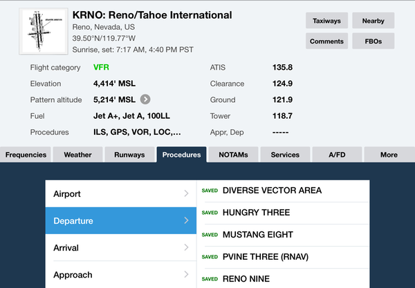
• Pilots should familiarize themselves with all the facilities and services available along the planned route of flight.
• Facilities: Runway length, Airport Elevation, Approaches, etc.
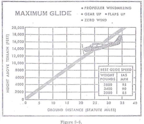
• Always know where the nearest VFR conditions can be found, and be prepared to head in that direction if the situation deteriorates or equipment malfunctions
Expected Performance: Aircraft
• ATC is expecting the aircraft to climb or descend at a minimum of 500 feet/minute
If unable, advise ATC as soon as possible
• When the aircraft is within 1000 feet of altitude, ATC is expected the aircraft to climb from 500 to 1500 feet / minute
• If cleared for a DP or STAR, follow the charted altitudes and airspeeds
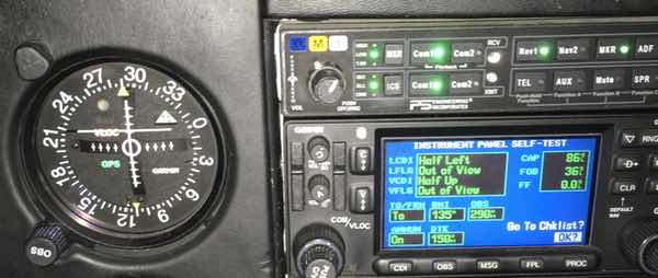
Required Equipment
• Must have VFR Day & Night Equipment in addition to:
• Required Aircraft IFR Equipment
– Generator (Alternator)
– Radios
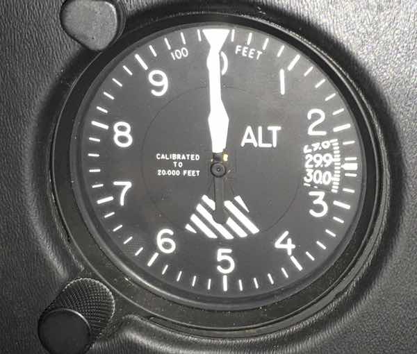
– Altimeter (Pressure Sensitive)
– Ball (Inclinometer)
– Clock (Second Hand Sweep)
– Attitude Indicator
– Rate of Turn Indicator
– Directional Gyro
– Do not need a VSI
• Required Inspections
– Annual Inspection
– 100-Hour Inspection (If for hire)
– Transponder (Every 24 Calendar Months)
– Altimeter (Every 24 Calendar Months)
– Pitot Static System (Every 24 Calendar Months)
– ELT (Every 24 Calendar Months)
– VOR (Every 30 Days)
– Acronym A1TAPEV
• VOR Checks
– Airborne Checkpoint (+/- 6°)
– Ground Checkpoint (+/- 4°)
– VOT (+/- 4°)
– Dual VORs (+/- 4° difference)
Alternates
§91.167 (b) (2) (i) For aircraft other than helicopters. For at least 1 hour before and for 1 hour after the estimated time of arrival, the ceiling will be at least 2,000 feet above the airport elevation and the visibility will be at least 3 statute miles.
1–2–3 Rule
• 1 hour before or after your ETA
• 2000 foot ceiling or below
• 3 miles visibility or below
Do I need an alternate? (FAR 91)
• No symbol – airport is good to go with standard alternate minimums.
 airport has nonstandard IFR alternate minimums Civil pilots should refer to the Alternate Minimums Section
 signifies that this approach is Not Authorized for use as an alternate due to unmonitored facility or the absence of weather reporting service.
• Depending on type of approach into the airport and the weather reported at the ETA
– Precision Approach – 600 foot ceiling and 2 miles visibility
– Non Precision Approach – 800 foot ceiling and 2 miles visibility
– No Published Approach – 1000 foot ceiling and 3 miles visibility
§91.169 IFR flight plan: Information required.
(c) IFR alternate airport weather minima. Unless otherwise authorized by the Administrator, no person may include an alternate airport in an IFR flight plan unless appropriate weather reports or weather forecasts, or a combination of them, indicate that, at the estimated time of arrival at the alternate airport, the ceiling and visibility at that airport will be at or above the following weather minima:
(1) If an instrument approach procedure has been published in part 97 of this chapter, or a special instrument approach procedure has been issued by the Administrator to the operator, for that airport, the following minima:
(i) For aircraft other than helicopters: The alternate airport minima specified in that procedure, or if none are specified the following standard approach minima:
(A) For a precision approach procedure. Ceiling 600 feet and visibility 2 statute miles.
(B) For a nonprecision approach procedure. Ceiling 800 feet and visibility 2 statute miles.
(2) If no instrument approach procedure has been published in part 97 of this chapter and no special instrument approach procedure has been issued by the Administrator to the operator, for the alternate airport, the ceiling and visibility minima are those allowing descent from the MEA, approach, and landing under basic VFR.
§91.155 Basic VFR weather minimums.
(c) Except as provided in §91.157, no person may operate an aircraft beneath the ceiling under VFR within the lateral boundaries of controlled airspace designated to the surface for an airport when the ceiling is less than 1,000 feet.
(d) Except as provided in §91.157 of this part, no person may take off or land an aircraft, or enter the traffic pattern of an airport, under VFR, within the lateral boundaries of the surface areas of Class B, Class C, Class D, or Class E airspace designated for an airport—
(1) Unless ground visibility at that airport is at least 3 statute miles; or
(2) If ground visibility is not reported at that airport, unless flight visibility during landing or takeoff, or while operating in the traffic pattern is at least 3 statute miles.
• How low can I go at the alternate?
– Precision Approach – 200 foot ceiling and 1/2 mile visibility
– Non Precision Approach – 400 foot ceiling and 1 mile visibility
– The minimums published on the approach
Airport Environment
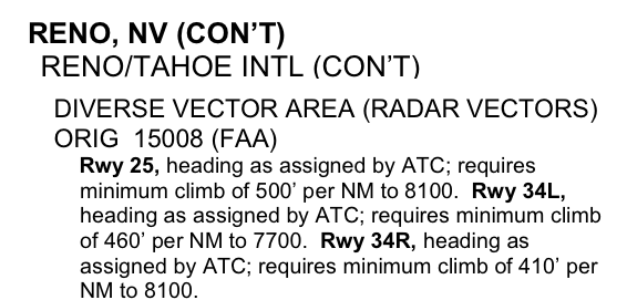
• Takeoff Minimums
– In the event of an emergency, a decision must be made to either return to the departure airport or fly directly to a takeoff alternate.
– The FAA establishes takeoff minimums for every airport that has published Standard Instrument Approaches. Legally, under 14 CFR 91 a zero/zero departure may be made, but it is never advisable.
§91.175 Takeoff and landing under IFR.
(f) Civil airport takeoff minimums. This paragraph applies to persons operating an aircraft under part 121, 125, 129, or 135 of this chapter.
(1) Unless otherwise authorized by the FAA, no pilot may takeoff from a civil airport under IFR unless the weather conditions at time of takeoff are at or above the weather minimums for IFR takeoff prescribed for that airport under part 97 of this chapter.
(2) If takeoff weather minimums are not prescribed under part 97 of this chapter for a particular airport, the following weather minimums apply to takeoffs under IFR:
(i) For aircraft, other than helicopters, having two engines or less—1 statute mile visibility.
(ii) For aircraft having more than two engines— 1⁄2 statute mile visibility.
(iii) For helicopters— 1⁄2 statute mile visibility.
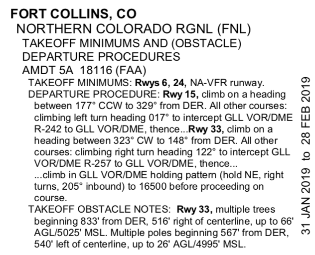
• AeroNav charts list takeoff minimums only for the runways at airports that have other than standard minimums. These takeoff minimums are listed by airport in alphabetical order in the front of the TPP booklet.
• If an airport has non-standard takeoff minimums, a  will be placed in the notes sections of the instrument procedure chart.
Airport Diagrams
• For select airports, AeroNav prints an airport diagram.
If you don’t have access to them in your EFB, you can download them from the FAA
– It is a full page depiction of the airport that includes the same features of the airport sketch plus additional details such as taxiway identifiers, airport latitude and longitude, and building identification.
– The airport diagrams are also available in the Airport / Facility Directory Chart Supplement
– The sketch is depicted in the lower left or right of an IAP.
– It depicts the runways, their length, width, and slope, the touchdown zone elevation, the lighting system installed on the end of the runway, and taxiways.
Fuel & Delays
• Aircraft must have enough fuel to reach your destination, fly to your alternate, with an additional 45 minutes at cruise power
ASRS Callback
A “fuel emergency” declaration is not defined in the Aeronautical Information Manual (AIM) or Federal Aviation Regulations, but is widely understood in the industry to mean a condition in which in the judgment of the pilot-in-command, it is necessary to proceed directly to the airport of intended landing due to low fuel. Use of this term conveys an explicit understanding that priority handling by ATC is both required and expected.
In contrast, the AIM (section 5-5-15) and Pilot/Controller Glossary provide the following definition of a “minimum fuel” declaration: “Indicates an aircraft’s fuel supply has reached a state where, upon reaching the destination, it can accept little or no delay. This is not an emergency situation but merely indicates an emergency situation is possible should any undue delay occur.”
The ATC Handbook (ATP 7110.65P: 2-1-8) adds the following guidance for controllers:
“A minimum fuel advisory does not imply a need for traffic priority. Common sense and good judgment will determine the extent of assistance to be given in minimum fuel situations.”
• Fuel Emergencies
– Declaring minimum fuel means you cannot accept undue delay in your flight
– Declaring an emergency and landing safely will not result in talking to the FAA
– However declaring and emergency and NOT landing safely, or refusing to declare and emergency and NOT landing safety will result in talking to the FAA
SIDs and STARs
• Departure procedures are preplanned routes that provide transitions from the departure airport to the en route structure.
– They also allow for efficient routing of traffic and reductions in pilot/controller workloads.
– Departure design criterion assumes an initial climb of 200 feet per nautical mile after crossing the departure end of the runway (DER) at a height of at least 35 feet and no turns before 400′ AGL
• There are two types of DPs: Obstacle Departure Procedures (ODPs) and Standard Instrument Departures (SIDs)
• Obstacle Departure Procedures (ODPs) are only used for obstruction clearance and do not include ATC related climb requirements. An ODP must be developed when obstructions penetrate the 40:1 departure plain.
• SIDS are designed at the request of ATC in order to increase capacity of terminal airspace. The primary goal is to reduce ATC/pilot workload while providing seamless transitions to the en route structure
• DPs are also categorized by equipment requirements as follows:
– Non-RNAV DP. Established for aircraft equipped with conventional avionics using ground-based NAVAIDs
– RNAV DP. Established for aircraft equipped with RNAV avionics; e.g., GPS, VOR/DME, etc. Automated vertical navigation is not required. Prior to using GPS, RAIM availability should be checked with the receiver or a Flight Service Station
Standard Instrument Departures
– Radar DP. Radar SIDs are established when ATC has a need to vector aircraft on departure to a particular route, NAVAID, or Fix. Radar vectors may also be used to join conventional or RNAV navigation SIDs
Departure Procedure Responsibility
• Responsibility for the safe execution of departure procedures rests on the shoulders of both ATC and the pilot.
• ATC is responsible for specifying the direction of takeoff or initial heading when necessary, and including departure procedures as part of the ATC clearance when pilot compliance for separation is necessary.
• The pilot must acknowledge receipt and understanding of an ATC clearance, request clarification of clearances, request an amendment to a clearance if it is unacceptable from a safety perspective or cannot be complied with.
Departures from Tower-Controlled Airports
– Normally you request your IFR clearance through ground control or clearance delivery
– Once you have received your clearance, it is your responsibility to comply with the instructions as given and notify ATC if you are unable to comply with the clearance
– Communication frequencies for the various controllers are listed on departure, approach, and airport charts as well as the A/FD.
Departures from Airports Without an Operating Control Tower
– You should file your flight plan at least 30 minutes in advance
– During your planning phase, investigate the departure airport’s method for receiving an instrument clearance.
– You can contact the Flight Service Station on the ground by telephone and they will request your clearance from ATC
– You must depart the airport before the clearance void time; if you fail to depart, you must contact ATC by a specified notification time
AIM 5−2−8. Instrument Departure Procedures (DP) − Obstacle Departure Procedures (ODP) and Standard Instrument Departures (SID)
1. Unless specified otherwise, required obstacle clearance for all departures, including diverse, is based on the pilot crossing the departure end of the runway at least 35 feet above the departure end of run- way elevation, climbing to 400 feet above the departure end of runway elevation before making the initial turn, and maintaining a minimum climb gradient of 200 feet per nautical mile (FPNM), unless required to level off by a crossing restriction, until the minimum IFR altitude.
ODPs are recommended for obstruction clearance and may be flown without ATC clearance unless an alternate departure procedure (SID or radar vector) has been specifically assigned by ATC.
Ground Communications Outlets
– This has been developed in conjunction with the capability to contact ATC and AFSS via VHF radio to a telephone connection to obtain an instrument clearance or close a VFR/IFR flight plan
– You can use four key clicks on your VHF radio to contact the nearest ATC facility and six key clicks to contact the local AFSS, but it is intended to be used only as a ground operational tool
– The GCO should help relieve the need to use the telephone to call ATC and the need to depart into marginal conditions just to achieve radio contact
– GCO information is listed on airport charts and instrument approach charts with other communications frequencies
Standard Terminal Arrival Routes
• The STAR provides a common method for leaving the en route structure and navigating to your destination
• Big differences between DPs and Stars
• DPs start at the pavement and connect to the en route structure. STARs on the other hand, start at the en route structure and they end at a fix or NAVAID
• Primarily STARs serve multiple airports
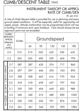
• STAR procedures typically include a standardized descent gradient at and above 10,000 feet MSL of 318 feet per NM, or 3 degrees
• If a speed reduction is needed a general guideline is typically to add 1 NM for each ten knots
– STARs usually are named according to the point at which the procedure begins
– The STAR name is usually the same as the last fix on the en route transitions
– A STAR that commences at the CHINS Intersection becomes the CHINS ONE ARRIVAL.
– When a significant portion of the arrival is revised, such as an altitude, a route, or data concerning the NAVAID, the number of the arrival changes. For example, the CHINS ONE ARRIVAL is now the CHINS FOUR ARRIVAL
– In addition, some STARs require that you use DME and/or ATC RADAR
AIM 5−4−1. Standard Terminal Arrival (STAR) Procedures
c. Use of STARs requires pilot possession of at least the approved chart. RNAV STARs must be retrievable by the procedure name from the aircraft database and conform to charted procedure. As with any ATC clearance or portion thereof, it is the responsibility of each pilot to accept or refuse an issued STAR.
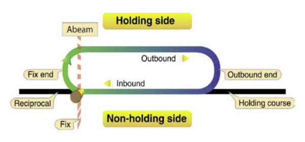
Holding Procedures
• Each holding pattern has a fix, a direction to hold, a course or radial, and the direction on which the aircraft is to hold
• Speed of the aircraft affects the size of a holding pattern therefore speed limits have been set depending on the altitude and ATC need
• Time plays another factor into a holding pattern. under 14,000 feet MSL, and 1 minute 30 seconds over 14,001 feet MSL.
• Time can be replaced by distance if the aircraft has DME or an IFR-certified GPS
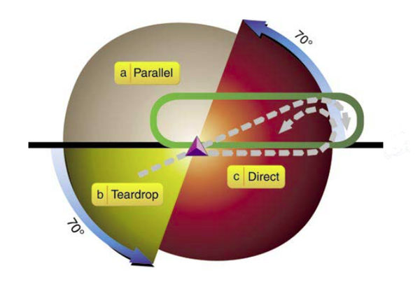
• There are 3 entries an aircraft can use to enter a hold. Originally the FAA mandated the entry, today you can enter every hold from a direct entry if you desire
Altitude (MSL)    Airspeed (KIAS)    Leg Time
MHA - 6,000'           200           1 minute
6,001' - 14,000’       230           1 minute 30 Seconds
14,001' and above      265           1 minute 30 Seconds
AIM 5-3-8. Holding
i. An ATC clearance requiring an aircraft to hold at a fix where the pattern is not charted will include the following information: (See FIG 5-3-2.)
1. Direction of holding from the fix in terms of the eight cardinal compass points (i.e., N, NE, E, SE, etc.).
2. Holding fix (the fix may be omitted if included at the beginning of the transmission as the clearance limit).
3. Radial, course, bearing, airway or route on which the aircraft is to hold.
4. Leg length in miles if DME or RNAV is to be used (leg length will be specified in minutes on pilot request or if the controller considers it necessary).
5. Direction of turn if left turns are to be made, the pilot requests, or the controller considers it necessary.
6. Time to expect further clearance and any pertinent additional delay information.
Enroute Procedures
• Course To Be Flown
– Part 91.181 is the basis for the course to be flown
– Pilots must either fly along the centerline on an airway or, along the direct course between navigational aids
– The regulation also allows an aircraft to pass clear of other traffic in VFR conditions
§91.181 Course to be flown.
Unless otherwise authorized by ATC, no person may operate an aircraft within controlled airspace under IFR except as follows:
(a) On an ATS route, along the centerline of that airway.
(b) On any other route, along the direct course between the navigational aids or fixes defining that route. However, this section does not prohibit maneuvering the aircraft to pass well clear of other air traffic or the maneuvering of the aircraft in VFR conditions to clear the intended flight path both before and during climb or descent.
Airway Structure
1.) Lower Stratum – an airway structure that extends from the base of controlled airspace to FL180.
2.) Second Stratum – contains identifiable Jet Routes from FL180 to FL450
3.) Third Stratum – Random point-to-point navigation above FL450
Air Route Traffic Control Centers
– ARTCCs provide the central authority for issuing IFR clearances and nationwide monitoring of each IFR flight
– There are 20 ARTCCs in the United States, and each containing between 20 to 80 sectors
– Appropriate radar and communication sites are connected to the Centers by microwave links and telephone lines
– When climbing after takeoff, an IFR flight is either in contact with a radar equipped local departure control or, in some areas, an ARTCC facility
– As a flight transitions to the en route phase, pilots typically expect a handoff from departure control to a Center frequency if not already in contact with the Center
– Accepting radar vectors from controllers does not relieve pilots of their responsibility for keeping track of altitude and position when during each phases of flight changes, and to aid in the management of air traffic
Preferred IFR Routes
– Preferred IFR routes are designed to provide a flow of air traffic in the major terminal and en route flight environments
– These routes are published in the Airport/Facility Directory Chart Supplement for the low and high altitude stratum
– These help pilots to plan a route to minimize route mileage
– Routes beginning or ending with a fix indicate that pilots will be routed to these fixes via a SID, vectors, or a STAR
– Routes where several airports are in proximity they are listed under the principal airport and categorized as a metropolitan area; e.g., New York Metro Area.
– If more than one route is listed both routes have equal priority for use.
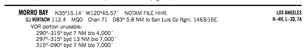
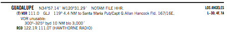
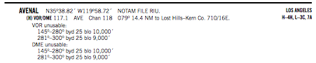
Monitoring of Navigation Facilities
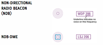
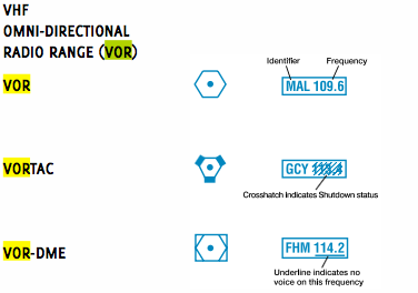
– VOR, VORTAC, VOR/DME, ILS facilities, NDBs, and Marker Beacons are provided with an internal monitoring feature
– Internal monitoring is provided at the facility through the use of equipment that causes a facility shutdown if performance deteriorates below established tolerances
– Older NDBs (both Federal and Non-Federal) do not have the internal feature and therefore are checked at least once each hour
– ARTCCs are usually the control point for NAVAID facility status.
– Pilots can also query the appropriate FAA facility if they have questions in flight regarding NAVAID status, or by checking the NOTAMs prior to flight since NAVAIDs and associated monitoring equipment are continuously changing
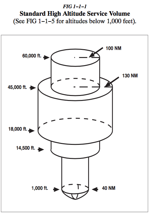
NAVAID Service Volume
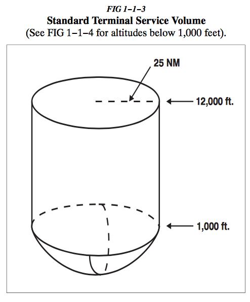
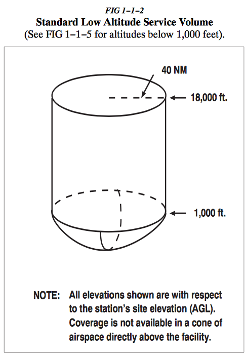
-Each class of NAVAID (VOR, VOR/DME, or VORTAC) has an established operational service volume to ensure adequate signal coverage and frequency protection
-When using VORs for direct route navigation, the following guidelines apply:
• For operations that are off airways below 18,000 feet MSL, pilots should use aids not more than 80 NM apart
– If using GPS for the route, the pilot can fly outside the service volume of some NAVAIDs, during this operation, the pilot has a responsibility for staying on the authorized direct route
– ATC uses radar flight following for the purpose of aircraft separation. If ATC initiates a direct route that exceeds NAVAID service volume limits, ATC also provides radar navigational assistance as necessary
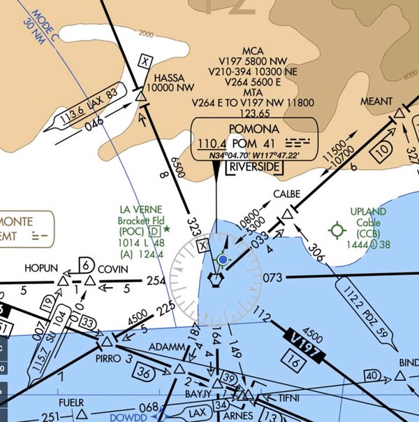
Changeover Points
– When flying airways, pilots normally change frequencies midway between navigation aids
– If the navigation signals cannot be received at the midpoint a COP is depicted and shows the distance in NM to each NAVAID
– COPs indicate the point where a frequency change is necessary to receive course guidance
– These change over points divide an airway or route segment and ensure continuous reception of navigation signals at the prescribed minimum en route IFR altitude
– Where radio frequency interference or other navigation signal problems exist, the COP is placed at the optimum location
IFR Enroute Altitudes
– For IFR operations, regulations require that pilots operate their aircraft at or above minimum altitudes
– Minimum altitude rules are designed to ensure safe vertical separation between the aircraft and the terrain
• Minimum Enroute Altitude
– This is the lowest published altitude that assures acceptable navigational signal coverage and meets obstacle clearance requirements
– MEAs are established based upon obstacle clearance over terrain and manmade objects, although adequate communication at the MEA is not guaranteed
• Minimum Obstruction Clearance Altitude
– This is the lowest published altitude in effect between VOR airways.
– This altitude assures acceptable navigational signal coverage only within 22 NM of a VOR
• Minimum Vectoring Altitude
– These are established for use by ATC when being vectored. The MVA provides 1,000 feet of clearance above the highest obstacle and 2,000 feet in designated mountainous areas
– Some MVAs may be lower than MEAs, or MOCAs depicted on charts for a given location
• Maximum Authorized Altitude
– This is a published altitude representing the maximum usable altitude for a route segment
– MAAs represent procedural limits determined by limitations of ground based facilities.
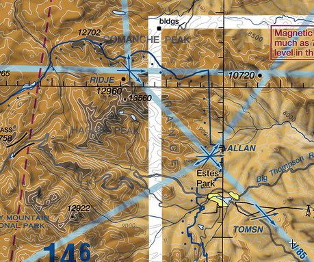
• Minimum Reception Altitude
– This is the minimum altitude that a navigation signal can be received for the route and for off- course NAVAID facilities that determine a fix
• Minimum Crossing Altitude
– This is the lowest altitude at certain fixes at which the aircraft must cross when proceeding in the direction of a higher minimum en route IFR altitude
– MCAs are established where obstacles intervene to prevent pilots from maintaining obstacle clearance
– The standard for determining the MCA is based upon the following climb gradients
Sea level through 5,000 feet MSL — 150 feet per NM
5000 feet through 10,000 feet MSL — 120 feet per NM
10,000 feet MSL and over — 100 feet per NM
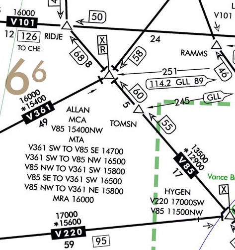
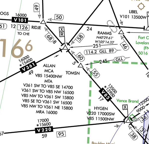
• Minimum Turning Altitude
– MTAs the published minimum enroute altitude (MEA) may not be sufficient for obstacle clearance when a turn is required over a fix, NAVAID, or waypoint.
– Pilots must ensure they are at or above the charted MTA not later than the turn point and maintain at or above the MTA until joining the centerline of the ATS route following the turn point. Once established on the centerline following the turning fix, the MEA/MOCA determines the minimum altitude available for assignment.
• Off Route Obstruction Clearance Altitude
– This route provides obstruction clearance with a 1,000-foot (non-mountainous) and 2,000-foot (mountainous areas)
– OROCAs are intended primarily as a pilot tool for emergencies and situational awareness
– This altitude may not provide signal coverage.
IFR Cruising Altitude & VFR-On-Top
– In controlled airspace, pilots must maintain the altitude assigned by ATC
– When operating with a VFR-on-top clearance, any VFR cruising altitude appropriate to the direction of flight that allows the flight to remain in VFR conditions
– Any change in altitude must be reported to ATC and pilots must comply with all other IFR reporting procedures
– VFR-on-top is not authorized in Class A airspace
Reporting Procedures
– These are reports that should be made without a specific request from ATC
• VFR-on-top change in altitude
• Missed approach
• Leaving one assigned flight altitude for another
• Leaving any assigned holding fix or point
• Unable to climb or descend at least 500 feet per minute
• TAS variation from filed speed of 5% or 10 knots, whichever is greater
• Time and altitude upon reaching a holding fix
• Loss of NAV/Comm capability
• Unforecasted weather conditions or other information relating to the safety of flight
Non RADAR Reports
– If radar contact has been lost the CFRs require pilots to provide ATC with position reports over designated VORs
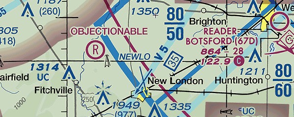
• Compulsory reporting points as depicted on IFR en route charts by solid triangles
• Leaving FAF or OM inbound on final approach
• Revised ETA of more than three minutes
Position Report
– Identification – (CPF 1256)
– Position–(FILMS)
– Time–(1215z)
– Altitude/FlightLevel–(5000)
– ETA over the next reporting fix – (MATAN IN 5 MIN)
– Following reporting point–(VHP VORTAC)
– Pertinent remarks
§91.187 Operation under IFR in controlled airspace: Malfunction reports.
(a) The pilot in command of each aircraft operated in controlled airspace under IFR shall report as soon as practical to ATC any malfunctions of navigational, approach, or communication equipment occurring in flight.
(b) In each report required by paragraph (a) of this section, the pilot in command shall include the—
(1) Aircraft identification;
(2) Equipment affected;
(3) Degree to which the capability of the pilot to operate under IFR in the ATC system is impaired; and
(4) Nature and extent of assistance desired from ATC.
Approach Procedures
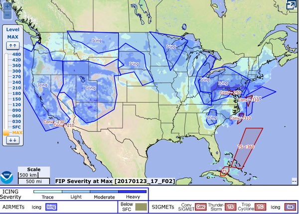
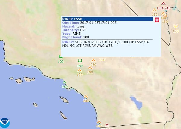
Weather Considerations
– Weather conditions generally determine which approaches can be used, or if an approach can even be attempted
– The primary concerns for approach decision-making are wind speed and direction, ceiling, visibility, and field conditions
– Wind speed and direction are factors because they often limit the type of approach that can be flown at a specific location
Approach Speed and Category
– Two other critical performance factors are: aircraft approach category and planned approach speed
– According to 14 CFR Part 97.3 (b), aircraft approach category is based on the landing speed (if not specified 1.3 VS0 at max gross weight)
– The categories are as follows:
• Category A: Speed less than 91 knots.
• Category B: Speed 91 knots or more but less than 121 knots.
• Category C: Speed 121 knots or more but less than 141 knots.
• Category D: Speed 141 knots or more but less than 166 knots.
• Category E: Speed 166 knots or more.
– An airplane is certified in only one approach category although a faster approach speed may be used
– If a faster approach speed is used the minimums for the appropriate higher category must be used
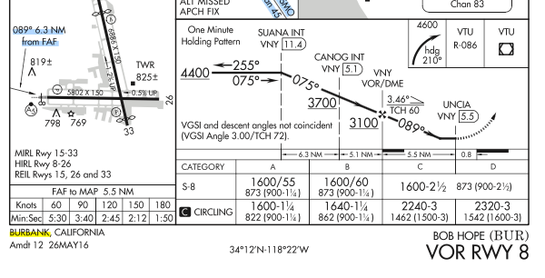
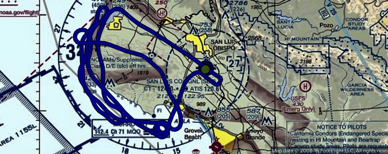
Circling Approaches
– An airplane cannot be flown to the minimums of a slower approach category
– Published circling minimums provide obstacle clearance only within the appropriate area of protection based on the approach category speed
– The circling approach area is the obstacle clearance area for airplanes maneuvering to land on a runway that does not meet the criteria for a straight-in approach
– A minimum of 300 feet of obstacle clearance is provided in the circling segment
– Pilots should remain at or above the circling altitude until the airplane is in a position from which a descent to a landing can be made
Chart Format – Chart Identification
– Procedures that allow a pilot to land straight in when conditions permit have a runway number in the chart identification
– Procedures without Straight-In Minimums have a letter after the type of approach
• Chart Format – Notes Section
– Non-Standard Takeoff Minimums, and Non- Standard Alternate Minimums
– Inoperative components
• Minimum Safe Altitude
– These are published for emergency use on IAP charts
– The MSA is normally based on the primary omnidirectional facility on which the IAP is predicated
– MSAs are expressed in feet MSL and normally have a 25NM radius
– Ideally, a single sector altitude is established and depicted on the planview of approach charts
– MSAs provide 1,000 feet clearance over all obstructions and may not have acceptable navigation signal coverage
• Chart Format – Vertical Navigation Information
• Chart Format – Vertical Guidance Approach Minimums
• Chart Format – Airport Sketch
Operations below DA, DH, or MDA
– No pilot may operate an aircraft below the MDA or the DH unless —
• (1) The aircraft must be in a position to make a normal landing straight in
• (2) The flight visibility is not less than the visibility prescribed in the approach procedure
• (3) At least one of the following visual references
– The threshold.
– The threshold markings
– The threshold lights
– The runway end identifier lights
– The visual approach slope indicator
– The touchdown zone or touchdown zone markings
– The touchdown zone lights
– The runway or runway markings
– The runway lights
– The approach light system only allow a pilot to descend 100 feet above the touchdown zone elevation using the approach lights as a reference
§91.175 Takeoff and landing under IFR.
(c) Operation below DA/ DH or MDA.… no pilot may operate an aircraft… below the authorized MDA or continue an approach below the authorized DA/DH unless—
(i) The approach light system, except that the pilot may not descend below 100 feet above the touchdown zone elevation using the approach lights as a reference unless the red terminating bars or the red side row bars are also distinctly visible and identifiable.
(ii) The threshold.
(iii) The threshold markings.
(iv) The threshold lights.
(v) The runway end identifier lights.
(vi) The visual approach slope indicator.
(vii) The touchdown zone or touchdown zone markings.
(viii) The touchdown zone lights.
(ix) The runway or runway markings.
(x) The runway lights.
Visual Approaches
– A visual approach is an ATC authorization for an aircraft on an IFR flight plan to proceed visually to the airport – it is not an IAP
– Once pilots report the aircraft in sight, they assume the responsibilities for their own separation and wake turbulence avoidance
– Also, there is no missed approach segment
– It is authorized when the ceiling is reported or expected to be at least 1,000 feet AGL and the visibility is at least 3 SM
– Pilots must remain clear of the clouds at all times while conducting a visual approach
Instrument Landing Systems
– A system that allows an aircraft both vertical and horizontal guidance to land in IMC conditions
ILS Approach Categories
– There are three general classifications of ILS approaches — CAT I, CAT II, and CAT III
• CAT I — DH 200 feet and RVR 2,400 feet
• CAT II — DH 100 feet and RVR 1,200 feet
• CAT IIIa — No DH or DH below 100 feet and RVR not less than 700 feet
• CAT IIIb — No DH or DH below 50 feet and RVR less than 700 feet but not less than 150 feet
• CAT IIIc — No DH and no RVR limitation
– To date, no U.S. operator has received approval for CAT IIIc approaches
VOR Approach
– VOR approaches use VOR facilities both on and off the airport to establish approaches
– All VOR approaches are non-precision approaches, and can provide MDAs as low as 250 feet above the runway
– VOR also offers a flexible advantage in that an approach can be made toward or away from the navigational facility
– When DME is included in the title of the VOR approach, operable DME must be installed in order to fly the approach
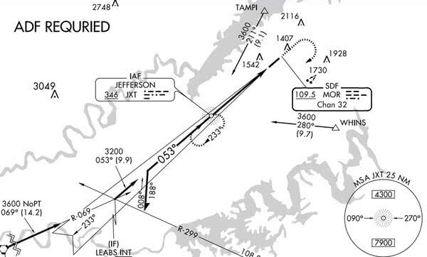
NDB Approach
– NDB approach can be designed using facilities both on and off the airport
– For the NDB to be considered an on-airport facility, the facility must be located within one mile of any portion of the landing runway
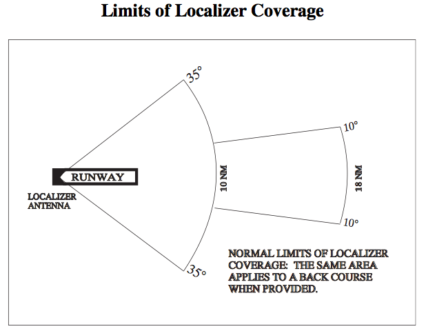
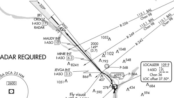
Localizer Approaches
– Typically, when the localizer is discussed, it is thought of as a nonprecision approach
– A localizer is always aligned within 3 degrees of the runway, and it is afforded a minimum of 250 feet obstacle clearance in the final approach area
Localizer Back Course
– In cases where an ILS is installed, a back course may be available in conjunction with the localizer
– The localizer approach system can provide both precision and nonprecision approach capabilities to a pilot
– In either case, the localizer provides an on precision approach using a localizer transmitter installed at a specific airport
– The back course does not offer a glide slope and it can project a false glide slope signal and should be ignored
– Reverse sensing will occur on the back course using standard VOR equipment
Equipment Problems • Communication Failure
– Two-way radio communication failure procedures for IFR operations are outlined in 14 CFR Part 91.185
– Pilots can use the transponder to alert ATC to a radio communication failure by squawking code 7600
– If only the transmitter is INOP, listen for ATC instructions on any operational receiver (This could also be any VOR, VOR / DME, VORTAC, ILS, or NDB frequency)
– If the radio fails in VFR conditions, continue the flight under VFR conditions and land as soon as practicable
– If pilots must continue their flight under IFR conditions after experiencing two-way radio communication failure, they should fly one of the following routes:
• 1.) The route assigned by ATC in the last clearance
• 2.) If being radar vectored, the direct route from the point of radio failure to the fix, route, or airway
• 3.) The route ATC has advised to expect in a further clearance
• 4.) The route filed in the flight plan.
– The altitude to fly after a communication failure can be found in Part 91.185
• The altitude in the last ATC clearance.
• The minimum altitude for IFR operations.
• The altitude ATC has advised to expect
§91.185 IFR operations: Two-way radio communications failure.
(a) General. Unless otherwise authorized by ATC, each pilot who has two-way radio communications failure when operating under IFR shall comply with the rules of this section.
(b) VFR conditions. If the failure occurs in VFR conditions, or if VFR conditions are encountered after the failure, each pilot shall continue the flight under VFR and land as soon as practicable.
(c) IFR conditions. If the failure occurs in IFR conditions, or if paragraph (b) of this section cannot be complied with, each pilot shall continue the flight according to the following:
(1) Route. (i) By the route assigned in the last ATC clearance received;
(ii) If being radar vectored, by the direct route from the point of radio failure to the fix, route, or airway specified in the vector clearance;
(iii) In the absence of an assigned route, by the route that ATC has advised may be expected in a further clearance; or
(iv) In the absence of an assigned route or a route that ATC has advised may be expected in a further clearance, by the route filed in the flight plan.
(2) Altitude. At the highest of the following altitudes or flight levels for the route segment being flown:
(i) The altitude or flight level assigned in the last ATC clearance received;
(ii) The minimum altitude (converted, if appropriate, to minimum flight level as prescribed in §91.121(c)) for IFR operations; or
(iii) The altitude or flight level ATC has advised may be expected in a further clearance.
(3) Leave clearance limit. (i) When the clearance limit is a fix from which an approach begins, commence descent or descent and approach as close as possible to the expect-further-clearance time if one has been received, or if one has not been received, as close as possible to the estimated time of arrival as calculated from the filed or amended (with ATC) estimated time en route.
(ii) If the clearance limit is not a fix from which an approach begins, leave the clearance limit at the expect-further-clearance time if one has been received, or if none has been received, upon arrival over the clearance limit, and proceed to a fix from which an approach begins and commence descent or descent and approach as close as possible to the estimated time of arrival as calculated from the filed or amended (with ATC) estimated time en route.