Instruments
Alternate static source:
Altimeter higher, Airspeed greater than actual, Momentary rise in VSI
Altimeter
High to low, look out below. Applies to pressure and temperature.
Altitude goes in the same direction as the pressure setting in the Kollsman window.
e.g 1″ decrease for each 1000′ decrease in altitude, 1″ increase for each 1000′ increase in altitude.
In colder than standard air temperature true altitude will be lower than indicated altitude with an altimeter setting of 29.92 inches Hg.
Inclinometer
In a turn made with a bank angle that is too steep, the force of gravity is greater than the inertia and the ball rolls down to the inside of the turn (slip). If the turn is made with too shallow a bank angle, the inertia is greater than gravity and the ball rolls upward to the outside of the turn (skid).
Return to coordinated flight from a skid, increase the bank angle and/or reduce the rate of turn with rudder.
Return to coordinated flight from a slip, decrease the bank angle and/or increase the rate of turn with rudder.
Airspeed
As altitude increases Vx increases.
As altitude increases Vy decreases.
Attitude indicator
There may be a slight nose-up indication during a rapid acceleration and a nose-down indication during a rapid deceleration. There is also a possibility of a small bank angle and pitch error after a 180° turn.
Directional gyro
Check, in straight and level flight, about every 15 minutes or after holding pattern.
Turn Coordinator
First shows the rate of bank, and once established, the rate of turn.
VOR
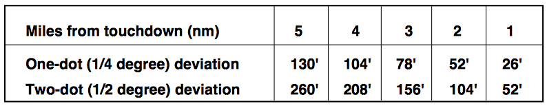
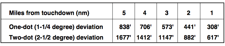
At 30 NM each dot is appoximately 1 NM displacement.
So 1 NM is ~200′.
Minutes to station = Time (seconds)/Bearing Change (degrees)
then Distance to station = True Airspeed (kts) * Time (seconds)
VOT
With the CDI centered, the OBS should read 0° showing FROM or 180° showing TO.
RMI indicates 180° TO on any OBS setting.
HSI
The slaving meter indicates the difference between the displayed heading and the magnetic heading. A right deflection indicates a clockwise error of the compass card; a left deflection indicates a counterclockwise error.
Fundamental Skills of Instrument Flying
Cross-check, Interpretation, Control
Unusual Attitude—Nose High
Add power, Reduce Pitch, Level the Wings – Leveling the wings first may result in a spin.
Unusual Attitude—Nose Low
Reduce power, Level the Wings, Increase Pitch – Increasing the pitch first will increase the bank and may overstress the airframe.
Wake Turbulence
Wingtip vortices are greatest when the generating aircraft is “heavy, clean, and slow.” This condition is most commonly encountered during approaches or departures because an aircraft’s AOA is at the highest to produce the lift necessary to land or take off.
Approach the runway above a preceding aircraft’s path when landing behind another aircraft and touch down after the point at which the other aircraft wheels contacted the runway.
Close to the ground (within 100 to 200 feet), they tend to move laterally over the ground at a speed of 2 or 3 knots. A wind speed of 10 knots causes the vortices to drift at about 1,000 feet in a minute in the wind direction.
Clear Air Turbulence
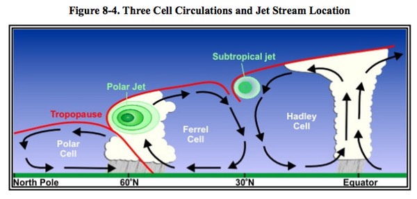
Moderate CAT is considered likely when the vertical wind shear is 5 kts per 1,000 feet or greater, and/or the horizontal wind shear is 40 kts per 150 miles or greater.
Jet streams stronger than 110 kts (at the core) have potential for generating significant turbulence near the sloping tropopause above the core, in the jet stream front below the core, and on the low-pressure side of the core.
Wind Shear
Directional wind changes of 180° and speed changes of 50 knots or more are associated with low-level wind shear. Low-level wind shear is commonly associated with passing frontal systems, thunderstorms, and temperature inversions with strong upper level winds (greater than 25 knots).
With a warm front, the most critical period is before the front passes.
When a constant tailwind shears to a calm or headwind, the plane’s airspeed increases causing the the nose to pitch up, and it has a tendency to go above the glide slope.
When a constant headwind shears to a calm or tailwind, the plane’s airspeed decreases causing the the nose to pitch down, vertical speed increases, and it has a tendency to go below the glide slope.
Microburst
Microburst activity may be indicated by an intense rain shaft at the surface but virga at cloud base and a ring of blowing dust is often the only visible clue. A typical microburst has a horizontal diameter of 1–2 miles and a nominal depth of 1,000 feet. The lifespan of a microburst is about 5–15 minutes during which time it can produce downdrafts of up to 6,000 feet per minute (fpm) and headwind losses of 30–90 knots,
Airport Markings
Threshold -> Touchdown Markings 500′
Threshold -> Aiming Point 1,000′
Threshold Markings -> 4 Stripes: 60′ to 16 Stripes: 200′
Centerline Stripe
Centerline lights are white until the last 3,000 feet of the runway. The white lights begin to alternate with red for the next 2,000 feet, and for the last 1,000 feet of the runway, all centerline lights are red.
Precision Runways have Touchdown Zone and Side Stripe
VASI provides obstacle clearance 4nm from threshold and 10° laterally.
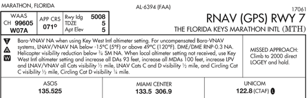
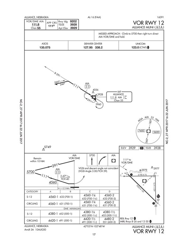
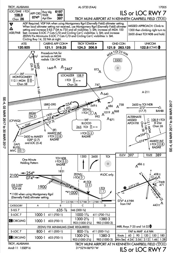
Touchdown zone elevation (TDZE). The highest elevation in the first 3,000 feet of the landing surface, TDZE is indicated on the instrument approach procedure chart when straight-in landing minimums are authorized.
Approach
Parallel ILS approaches provide aircraft a minimum of 1 1/2 miles radar separation between successive aircraft on the adjacent localizer course.
When the approach procedure involves a procedure turn, the maximum speed should not be greater than 200 kts.
The Glide Path Qualification Surface (GQS) limits the height of obstructions between the decision altitude and the runway threshold.
Stabilized approach: Straight in before FAF and before descending below 1,000′ AGL, Visual or circling before 500′ AGL
Engines spooled up, Descent less than 1,000 fpm, bank angle less than 15°
Approach Category
Aircraft approach category means a grouping of aircraft based on a speed of VREF, if specified, or if VREF is not specified, 1.3 VSO at the maximum certified landing weight.
    Category A: Speed less than 91 knots.                          1.3 NM Protected Area
    Category B: Speed 91 knots or more but less than 121 knots.    1.5 NM
    Category C: Speed 121 knots or more but less than 141 knots.   1.7 NM
    Category D: Speed 141 knots or more but less than 166 knots.   2.3 NM
    Category E: Speed 166 knots or more.                           4.5 NM
Expanded circling area (after 2012) varies by MSL.
Missed Approach
Missed approach obstacle clearance is assured only if the missed approach is commenced at the published MAP. Before initiating an IAP that contains a “Fly Visual to Airport” segment, the pilot should have preplanned climb out options based on aircraft performance and terrain features. Obstacle clearance is the responsibility of the pilot when the approach is continued beyond the MAP.
Holding
     Altitude (MSL)    Airspeed (KIAS)    Leg Time
     MHA - 6,000'           200           1 minute
     6,001' - 14,000’       230           1 minute 30 seconds
     14,001' and above      265           1 minute 30 seconds
Most GA aircraft use approach airspeed.
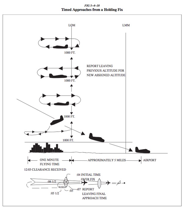
The pilot should begin outbound timing over or abeam the fix, whichever occurs later. If the abeam position cannot be determined, start timing when the turn to outbound is completed (wings level).
En Route
When ATC has not imposed any climb or descent restrictions and aircraft are within 1,000 feet of assigned altitude, pilots should attempt to both climb and descend at a rate of between 500 and 1,500′.
Hyperventilation
Breathing normally is both the best prevention and the best cure for hyperventilation. In addition to slowing the breathing rate, breathing into a paper bag or talking aloud helps to overcome hyperventilation.
Hypoxia
The reactions of the average person become impaired at an altitude of about 10,000 feet, but for some people impairment can occur at an altitude as low as 5,000 feet. The physiological reactions to hypoxia or oxygen deprivation are insidious and affect people in different ways. These symptoms range from mild disorientation to total incapacitation, depending on body tolerance and altitude.
Hypoxic hypoxia is a result of insufficient oxygen available to the body as a whole.
High altitude. CO2 in cabin from dry ice.
Hypemic hypoxia occurs when the blood is not able to take up and transport a sufficient amount of oxygen to the cells in the body.
CO poisoning, Blood donation. Bleeding. Smoking. Also called anemic hypoxia on the tests.
Stagnant hypoxia or ischemia results when the oxygen-rich blood in the lungs is not moving, for one reason or another, to the tissues.
Heart attack. Excessive acceleration of gravity (Gs). Cold temperatures can also reduce circulation and decrease the blood supplied to extremities.
Histotoxic hypoxia is the inability of the cells to effectively use oxygen.
Alcohol and other drugs, such as narcotics and poisons
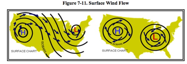
Weather
Unstable Air
Moist, unstable air causes cumulus clouds, showers, and turbulence to form.
Unstable air masses usually have good surface visibility.
Unstable air: Cumuliform clouds, Showery precipitation, Rough air (turbulence), Good Visibility.
Stable Air
A stable air mass can produce low stratus clouds and fog.
Stable air masses usually have poor surface visibility. The poor surface visibility is due to the fact that smoke, dust, and other particles cannot rise out of the air mass and are instead trapped near the surface.
Stable air; Stratiform clouds and fog, Continuous precipitation, Smooth air, Fair to poor visibility in haze and smoke.
Lapse Rates
Rising dry air cools at a lapse rate of 3°C per 1000′ (5.4°F). The dewpoint decreased .5°C (1°F) per 1000′.
Temperature and dew point converge at 2.5°C (4.4°F).
Moist adiabatic lapse rate, which varies between approximately 1.2°C per 1,000 feet for very warm saturated parcels to 3°C per 1,000 feet for very cold saturated parcels.
Average lapse rate is 2°C per 1,000′.
Squall
A sudden increase in wind speed by at least 15 knots to a peak of 20 knots or more and lasting for at least one minute. Essential difference between a gust and a squall is the duration of the peak speed. Wind speed variation of 10kts between peaks and lulls.
A squall line is a non-frontal, narrow band of active thunderstorms. Often it develops ahead of a cold front in moist, unstable air, but it may develop in unstable air far removed from any front. The line may be too long to easily detour and too wide and severe to penetrate. It often contains severe steady-state thunderstorms and presents the single most intense weather hazard to aircraft.
An airplane is most likely to be struck by lightning when the OAT is between -5°C and +5°C.
Icing
Freezing Drizzle— precipitation at ground level or aloft in the form of liquid water drops that have diameters less than 0.5 mm and greater than 0.05 mm. In freezing drizzle, the pilot cannot assume that a warm layer exists above the aircraft.
Freezing Rain—precipitation at ground level or aloft in the form of liquid water drops which have diameters greater than 0.5 mm. Freezing rain will result in ice forming in areas far aft of where it would normally form in icing conditions without freezing rain.
Supercooled Large Drops (SLD). Water drops with a diameter greater than 50 micrometers (0.05 mm) that exist in a liquid form at air temperatures below 0 °C.
Supercooled Clouds—Nearly all aircraft icing occurs in supercooled clouds. Liquid drops are present at outside air temperatures (OAT) below 0 °C (32°F) in these clouds. At temperatures below about -20°C (-4°F), most clouds are made up entirely of ice particles.
SLD may result in drops impinging aft of protected surfaces and causing ice accumulation behind the protected area of leading edges. These surfaces may be very effective ice collectors, and ice accumulations may persist as long as the aircraft remains in icing conditions.
Cloud water drops are generally very small, averaging 20 micrometers (.02 mm) in diameter, and are of such small mass that they can be held aloft by small air currents within clouds. If the temperatures are cold enough at the tops (below or around -15 °C (5 °F), ice particles will usually start to form that tend to deplete the liquid water.
Reporting Icing
Trace Icing—Ice becomes noticeable. The rate of accumulation is slightly greater than the rate of sublimation.
Light Icing—The rate of ice accumulation may create a problem if flight is prolonged in this environment (over 1 hour). Requires occasional cycling of manual deicing systems. 1⁄4 inch to 1 inch (0.6 to 2.5 cm) per hour on the outer wing.
Moderate Icing—Requires frequent cycling of manual deicing systems Anything more than a short encounter is potentially hazardous. 1 to 3 inches (2.5 to 7.5 cm) per hour on the outer wing.
Severe Icing—Ice protection systems fail to remove the accumulation of ice and accumulation occurs in areas not normally prone to icing. More than 3 inches (7.5 cm) per hour on the outer wing.
Clear Ice—Temperatures close to the freezing point, large amounts of liquid water, high aircraft velocities, and large drops are conducive to the formation of clear ice.
Rime Ice—Low temperatures, lesser amounts of liquid water, low velocities, and small drops favor formation of rime ice.
Carburetor Icing—May occur at temperatures between 20°F (-7°C) and 70°F (21°C).
Deicing
Boots—The amount of ice increases as airspeed or temperature decreases. The FAA recommends that the deicing system be activated at the first indication of icing.
Ice protection systems on airplanes certificated prior to 1973 should be considered a means to help exit icing conditions.
For small amounts of ice accretion, effects not apparent while operating in the middle of the flight envelope may be noticeable when operating at the edge of the flight envelope. The most common are an increase in stall speed (with a late or no warning) or the inability to climb at altitude.
Roll Upsets
Ice on the wings forward of the ailerons can affect roll control. The tips are usually thinner than the rest of the wing, and so they most efficiently collect ice. This can lead to a partial stall of the wings at the tips, which can affect the ailerons and thus roll control.
• Reduce the AOA by reducing the aircraft pitch. Roll the wings level.
• Set the appropriate power and monitor the airspeed and AOA.
• If the flaps are extended, do not retract them unless it can be determined that the upper surface of the airfoil is clear of ice. Retracting the flaps will increase the AOA at a given airspeed.
• Verify that the wing ice protection is functioning normally.
Tailplane Stall
An ice-contaminated tailplane stall typically occurs either while extending the wing trailing edge flaps to the landing position; with the flaps already extended to that position; or with the flaps already extended to that position when operating in, or departing from, icing conditions. Since flaps are normally only extended to the landing piosition during final approach to landing, tailplane stalls as the result of ice accumulation are most common in this phase of flight.
Elevator control pulsing, oscillations, or vibrations as well as any other unusual or abnormal pitch anomalies (possibly resulting in pilot-induced oscillations) are indicative of tailplane ice accumulation and the potential for a tailplane stall. You should retract the flaps to the last safe setting in this situation.
Blocked Pitot/Static System Effects
If the pitot tube inlet becomes blocked, air already in the system will vent through the drain hole, and the remaining will drop to ambient (i.e., outside) pressure. Airspeed indicator decreases to zero.
If the pitot tube, drain hole, and static system all become blocked in flight changes in airspeed will not be indicated, due to the trapped pressures.
If the static system remains clear, the airspeed indicator would display a higher than-actual airspeed as the altitude increased. As altitude is decreased, the airspeed indicator would display a lower-than-actual airspeed.
If the static port becomes blocked, the airspeed indicator would still function; however, it would be inaccurate. At altitudes above where the static port became blocked, the airspeed indicator would indicate a lower-than-actual airspeed. At lower altitudes, the airspeed indicator would display a higher-than-actual airspeed.
The trapped air in the static system would cause the altimeter to remain at the altitude where the blockage occurred.
If an alternate source is vented inside the airplane, where static pressure is usually lower than outside static pressure, selection of the alternate source may result in the following erroneous instrument indications: The altimeter reads higher than normal, the indicated airspeed reads greater than normal, the vertical speed indicator momentarily shows a climb.
Icing conditions in stratiform clouds often are confined to a relatively thin layer, either climbing or descending may be effective in exiting the icing conditions within the clouds. Icing encountered in cumulus clouds may be of limited duration; it may be possible to deviate around the cloud.
Weather Products
ATIS
Absence of the sky condition and visibility on an ATIS broadcast specifically implies that the ceiling is more than 5,000 feet and visibility is 5 miles or more.
TAF
The body of a Terminal Aerodrome Forecast (TAF) covers a geographical proximity within a 5 statute mile radius from the center of an airport runway complex.
Area Forecast (FA)
It was replaced by Graphic Area Forecasts (GFA) in 2017.
“WND” is appended to any category if the sustained surface wind is expected to be 20 kts or more, or surface wind gusts are expected to be 25 kts or more during the majority of the 6-hour outlook period.
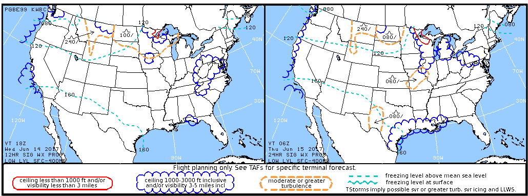
The VFR CLDS/WX section describes conditions consisting of MVFR cloud ceilings (1,000 to 3,000 feet AGL), MVFR obstructions to visibility (3-5 statute miles), and any other significant VFR clouds (bases at or below FL180) or VFR precipitation.
Wind and Temperature Aloft Forecast (FB)
The symbolic form of the forecasts is DDff+TT in which DD is the wind direction, ff the wind speed, and TT the temperature. Wind direction is indicated in tens of degrees (two digits) with reference to true north and wind speed is given in knots (two digits). Light and variable wind or wind speeds of less than 5 knots are expressed by 9900. Forecast wind speeds of 100 through 199 knots are indicated by adding 100 to the speed and subtracting 50 from the coded direction.
No winds forecast within 1,500′ of station elevation. No temp within 2,500′ of reporting and 3,000′ level.
Temps are negative above 24,000′
Weather Depiction Chart
The Weather Depiction Chart is being phased out by the NWS, in favor of newer ceiling and visibility products, like the CVA product.
Weather Advisory
A warning of hazardous weather conditions not predicted in the forecast area that may affect air traffic operations.
AIRMET, SIGMET
An AIRMET is a weather advisory issued only to amend the area forecast concerning weather phenomena which are of operational interest to all aircraft and potentially hazardous to aircraft having limited capability because of lack of equipment, instrumentation, or pilot qualifications. A SIGMET is a weather advisory issued concerning weather significant to the safety of all aircraft.
AIRMETs and SIGMETs are considered to be widespread because they must be affecting or be forecast to affect an area of at least 3000 square miles at any one time.
AIRMET
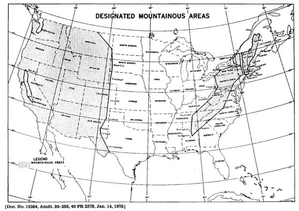
Sierra—Instrument Flight Rules (IFR) or Mountain Obscuration—Ceilings less than 1000 feet and/or visibility less than 3 miles affecting over 50% of the area at one time. Extensive mountain obscuration
Tango—Turbulence, Moderate Turbulence, Sustained surface winds of greater than 30 knots at the surface
Zulu—Icing, Moderate icing, Freezing levels
Routinely issued for 6 hour periods.
SIGMET—Severe Icing, Severe or Extreme Turbulence, Dust storms and/or sand storms lowering visibilities to less than three (3) miles, Volcanic Ash. Issued for 6 hour periods for conditions associated with hurricanes and 4 hours for all other events.
Convective SIGMETs—Severe surface weather including: surface winds greater than or equal to 50 knots, hail at the surface greater than or equal to 3/4 inches in diameter, tornadoes, embedded thunderstorms, line of thunderstorms, thunderstorms greater than or equal to VIP level 4 affecting 40% or more of an area at least 3000 square miles. Valid for up to 2 hours.
CWAs are advisories issued by the Center Weather Service Units (CWSUs) that are for conditions just below severe criteria. CWAs are issued for: Thunderstorms, Turbulence, Icing, Ceiling & Visibility (IFR)
Vestibular Illusions
The Leans
When a banked attitude, to the left for example, may be entered too slowly to set in motion the fluid in the “roll” semicircular tubes. An abrupt correction of this attitude sets the fluid in motion, creating the illusion of a banked attitude to the right.
Coriolis Illusion
The coriolis illusion occurs when a pilot has been in a turn long enough for the fluid in the ear canal to move at the same speed as the canal. A movement of the head in a different plane, such as looking at something in a different part of the flight deck, may set the fluid moving and create the illusion of turning or accelerating on an entirely different axis.
Graveyard Spiral
A pilot in a prolonged coordinated, constant-rate turn, will have the illusion of not turning. During the recovery to level flight, the pilot experiences the sensation of turning in the opposite direction.
Somatogravic Illusion
A rapid acceleration, such as experienced during takeoff, stimulates the otolith organs in the same way as tilting the head backwards. This action creates the somatogravic illusion of being in a nose-up attitude.
Inversion Illusion
An abrupt change from climb to straight-and-level flight can stimulate the otolith organs enough to create the illusion of tumbling backwards or inversion illusion.
Elevator Illusion
An abrupt upward vertical acceleration, as can occur in an updraft, can stimulate the otolith organs to create the illusion of being in a climb.
Turning Illusions
Without visual aid, a pilot often interprets centrifugal force as a sensation of rising or falling.
While in the turn, without outside visual references and under the effect of the slight positive G, the usual illusion produced is that of a climb. On recovery from the turn, at approximately one-half completed the usual illusion will be that the aircraft is diving.
Visual Illusions
False Horizon
A sloping cloud formation, an obscured horizon, an aurora borealis, a dark scene spread with ground lights and stars, and certain geometric patterns of ground lights can provide inaccurate visual information, or false horizon, for aligning the aircraft correctly with the actual horizon.
Autokinesis
In the dark, a stationary light will appear to move about when stared at for many seconds.
Optical Illusions
Runway and Terrain Slopes Illusion
A narrower-than-usual or an upsloping runway, upsloping terrain can create an illusion the aircraft is at a higher altitude than it actually is.
Featureless Terrain Illusion
An absence of surrounding ground features, as in an overwater approach, over darkened areas, or terrain made featureless by snow, can create an illusion the aircraft is at a higher altitude than it actually is.
Water Refraction
Rain on the windscreen can create an illusion of being at a higher altitude due to the horizon appearing lower than it is.
Haze
Atmospheric haze can create an illusion of being at a greater distance and height from the runway.
Fog
Flying into fog can create an illusion of pitching up.
Ground Lighting Illusions
Lights along a straight path, such as a road or lights on moving trains, can be mistaken for runway and approach lights.
ATC Reports
Reports
Reports that should be made without a specific request from ATC
• VFR-on-top change in altitude
• Missed approach
• Leaving one assigned flight altitude for another
• Leaving any assigned holding fix or point
• Unable to climb or descend at least 500 feet per minute
• TAS variation from filed speed of 5% or 10 knots, whichever is greater
• Time and altitude upon reaching a holding fix
• Loss of NAV/Comm capability
• Unforecasted weather conditions or other information relating to the safety of flight
Readback of airborne clearance
Q:What response is expected when ATC issues an IFR clearance to pilots of airborne aircraft?
A: Read back those parts containing altitude assignments or vectors and any part requiring verification.
Non RADAR Reports
If radar contact has been lost the CFRs require pilots to provide ATC with position reports over designated VORs
• Compulsory reporting points as depicted on IFR en route charts by solid triangles
• Leaving FAF or OM inbound on final approach
• Revised ETA of more than three minutes
Miscellaneous Things I Can’t Remember
An abbreviated departure clearance, …Cleared as Filed…, will always contain the destination airport (or clearance limit), en route altitude, advise to expect an assigned altitude or filed altitude at a certain point after departure. It also includes the Departure Procedure if appropriate.
To level off at an airspeed higher than the descent speed, the addition of power should be made, assuming a 500 FPM rate of descent, at approximately 100 to 150 feet above the desired altitude.
If severe turbulence is encountered during your IFR flight, the airplane should be slowed to the design maneuvering speed because the amount of excess load that can be imposed on the wing will be decreased.
Types of NOTAMs.
FDC NOTAMs Advise of changes in flight data which affect instrument approach procedure (IAP), aeronautical charts, and flight restrictions prior to normal publication.
NOTAM (D) Consists of information that requires wide dissemination via telecommunication and pertains to: En Route navigational aids, Civil public-use airports listed in the Airport Facility Directory (AFD), Facilities Services
NOTAM (L) information pertinent to the departure and/or local area—Discontinued except for military.
ATC may request a detailed report of an emergency even though a rule has not been violated when priority has been given.


 is placed in the notes sections of the instrument procedure chart. In the front of the TPP booklet, takeoff minimums are listed before the obstacle departure procedure.
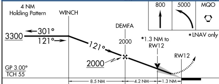
